DIY Meshtastic LoRa Node
One day I stumbled upon LoRa radio communication and the popular Meshtastic project. I’ve tinkered with GMRS radios before, and this seemed like something in that vein but with more opportunities for DIY electronics.
I won’t give a full breakdown of LoRa and Meshtastic, but here’s the basics:
- LoRa “nodes” running the Meshtastic firmware create a mesh which messages can be passed through
- At the bare minimum a LoRa node needs a MCU and a radio module
- LoRa can run completely off-grid with no licenses or subscriptions
Meshtastic Options
There are a few options for getting started with LoRa + Meshtastic.
The first is simply buying a fully assembled node. There’s a ton of options here, from tiny nodes that are pretty much a chip and an antennae, to all-in-one solutions that mimic old BlackBerry designs, allowing the user to compose messages directly on the device.
The second option is buying a development board like the Heltec V3 or others. These boards give you the main MCU (usually a ESP32 I think), the radio module (usually a SX1262), and in the case of the Heltec a built-in OLED. Some kits come with a lithium battery and a case, while some builders will opt for supplying their own battery and 3D printing a custom case.
I started with a small Heltec-based kit for my first node, but quickly grew interested in building a node “from scratch” (in this case, “from scratch” means providing my own MCU and radio module, rather than relying on a pre-built board, and seeing if I can connect the components and run Meshtastic).
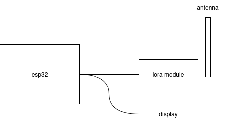
Basic Design
I wanted my first DIY node to be as simple as possible while still easy to debug. The basic setup I was targeting would be a microcontroller (ESP32), a LoRa radio module (SX1262), and a small display (SSD1306).
Shopping List
Throughout the design process, I was curious to see how my DIY build would compare to a kit cost-wise. At the time of writing, the Heltec V3 is \$18 (plus shipping). My AliExpress order for the ESP32 (\$5), radio module (\$7), and display (\$2) came out to \$14 (free shipping on orders over \$10). So not a huge difference, but there’s also some options for cost savings if I chose a smaller ESP32 rather than the DevKit that provides more pins.
The biggest cost was that radio module (often labeled DX-LR30 on AliExpress), because it seems most SX1262s are sold as SMD components or sold with other boards.
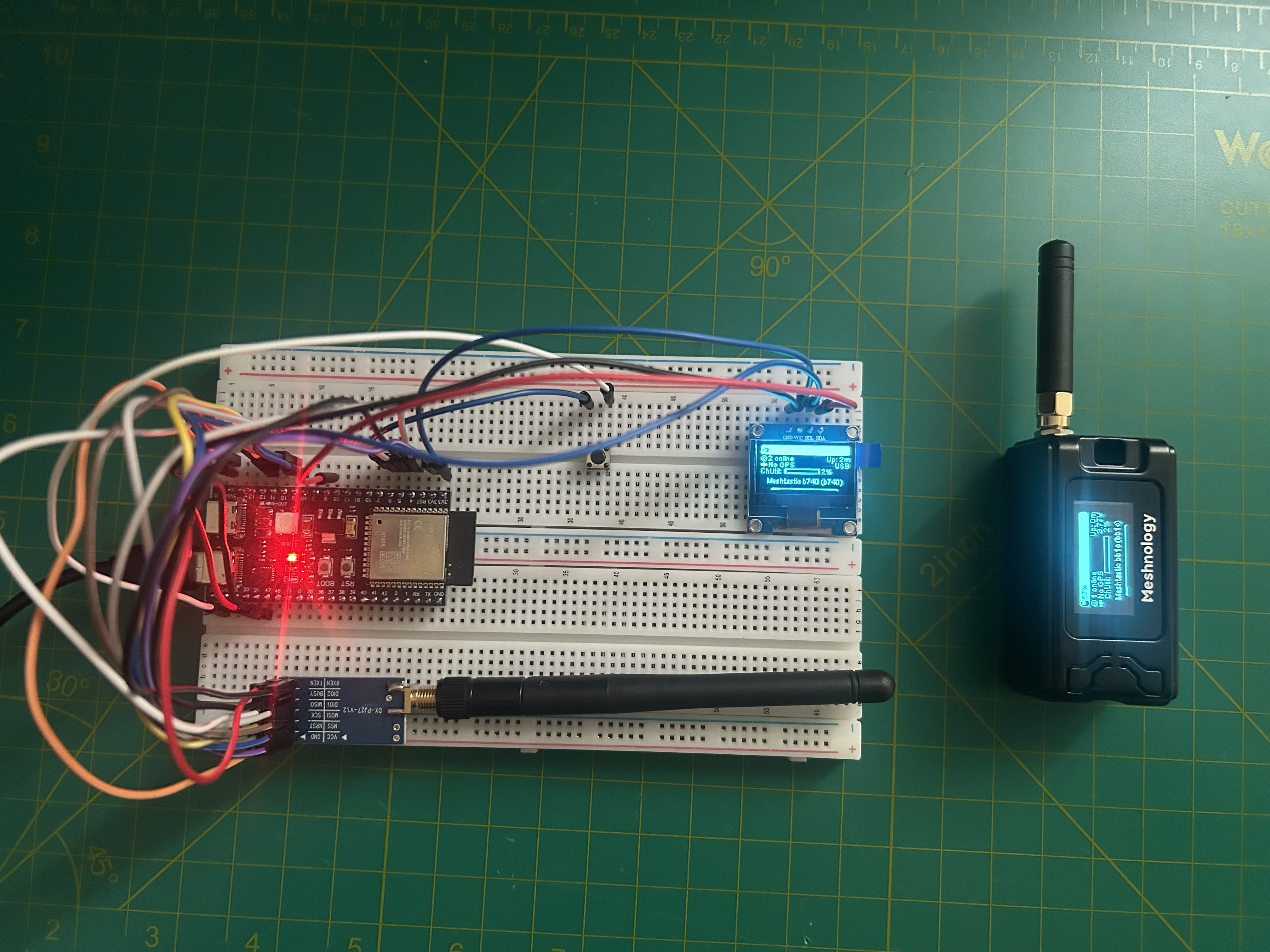
Breadboarding
After gathering my components, I was ready to build this on the breadboard. As shown in the basic design, the layout of the circuit is mostly a matter of connecting the ESP32 to the display and to the radio module. Although not required, I also added a push button to the cicuit that will allow me to interact with the Meshtastic menu later.
For the most part, any ol’ GPIO pin works for connecting to the radio and display since we will define the pin mappings in the firmware. We can use any of the GND pins, and both the radio and display use the 3v3 pin for power (don’t use 5V!).
Here’s my pin configuration:
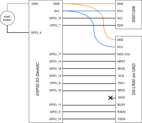
NOTE: There are a ton of different ESP32 variants, so unless you are using the same ESP32-S3-DevKitC like me, your pin options will be different. In my case, I chose random GPIO pins at first, then adjusted them to make my stripboard layout easier (more on that later).
Dev Environment Setup
Because this is a custom configuration and not a pre-built board that is supported by Meshtastic by default, I couldn’t use the standard Meshtastic firmware and flasher. Instead, I needed to create a custom variant of the Meshtastic firmware.
And of course before doing any custom firmware work, there’s a few tools I needed to install:
- VSCode (I usuallly use the open-source VSCodium, but to avoid any extension issues I used the real deal for this project)
- PlatformIO, which is installed via extension within VSCode
Firmware Development
Once my development environment was ready, I was ready to start customizing the firmware. Luckily I found this GitHub repo that walked me through most of this process.
Step 1 – Project Setup
#
# download the firmware repo
#
git clone https://github.com/meshtastic/firmware

#
# open the repo up in VSCode (with the PlatformIO extension ready to go)
#
cd firmware && code .

#
# 'variants' contains all the different firmwares, so made a folder for my firmware
#
mkdir variants/diy_esp32
Step 2 – Add Two Files
Within my variants/diy_esp32 folder, I added the following files:
//
// variant.h
//
#ifndef _VARIANT_DIY_ESP_H_
#define _VARIANT_DIY_ESP_H_

#define BUTTON_PIN 4
// #define LED_PIN 8

#define USE_SX1262

#define LORA_CS 17
#define LORA_MOSI 18
#define LORA_SCK 13
#define LORA_MISO 12

#define LORA_DIO1 8
#define LORA_BUSY 11
#define LORA_RESET 14

#define SX126X_CS    LORA_CS
#define SX126X_DIO1  LORA_DIO1
#define SX126X_BUSY  LORA_BUSY
#define SX126X_RESET LORA_RESET

#define I2C_SDA 7
#define I2C_SCL 15

#endif
//
// pins_arduino.h
//
#ifndef Pins_Arduino_h
#define Pins_Arduino_h

#include <stdint.h>

static const uint8_t TX = 10;
static const uint8_t RX = 9;

static const uint8_t SDA = 7;
static const uint8_t SCL = 15;

static const uint8_t SS    = 17;
static const uint8_t MOSI  = 18;
static const uint8_t SCK   = 13;
static const uint8_t MISO  = 12;

#endif
After this step, my project was looking like this:
firmware/
├── variants/
│   └── diy_esp32/
│       ├── variant.h
│       └── pins_arduino.h
└── ...
Step 3 – Add Entry to platformio.ini
The last edit was adding an entry to the platformio.ini, which from what I can tell, tells the extension how and what to build.
So at the bottom of platformio.ini I added the following:
[env:diy-esp32]
extends = esp32s3_base
board = esp32-s3-devkitc-1
board_build.variants_dir = variants
board_build.variant = diy_esp32

build_flags =
  ${esp32s3_base.build_flags}
  -DARDUINO_USB_MODE=1
  -DARDUINO_USB_CDC_ON_BOOT=1
  -I variants/diy_esp32

lib_deps =
  ${esp32s3_base.lib_deps}
NOTE: Be sure to select a valid board type (docs) and extend from the proper base (which can be found by poking around in the variants folders).
Step 4 – Upload and Monitor!
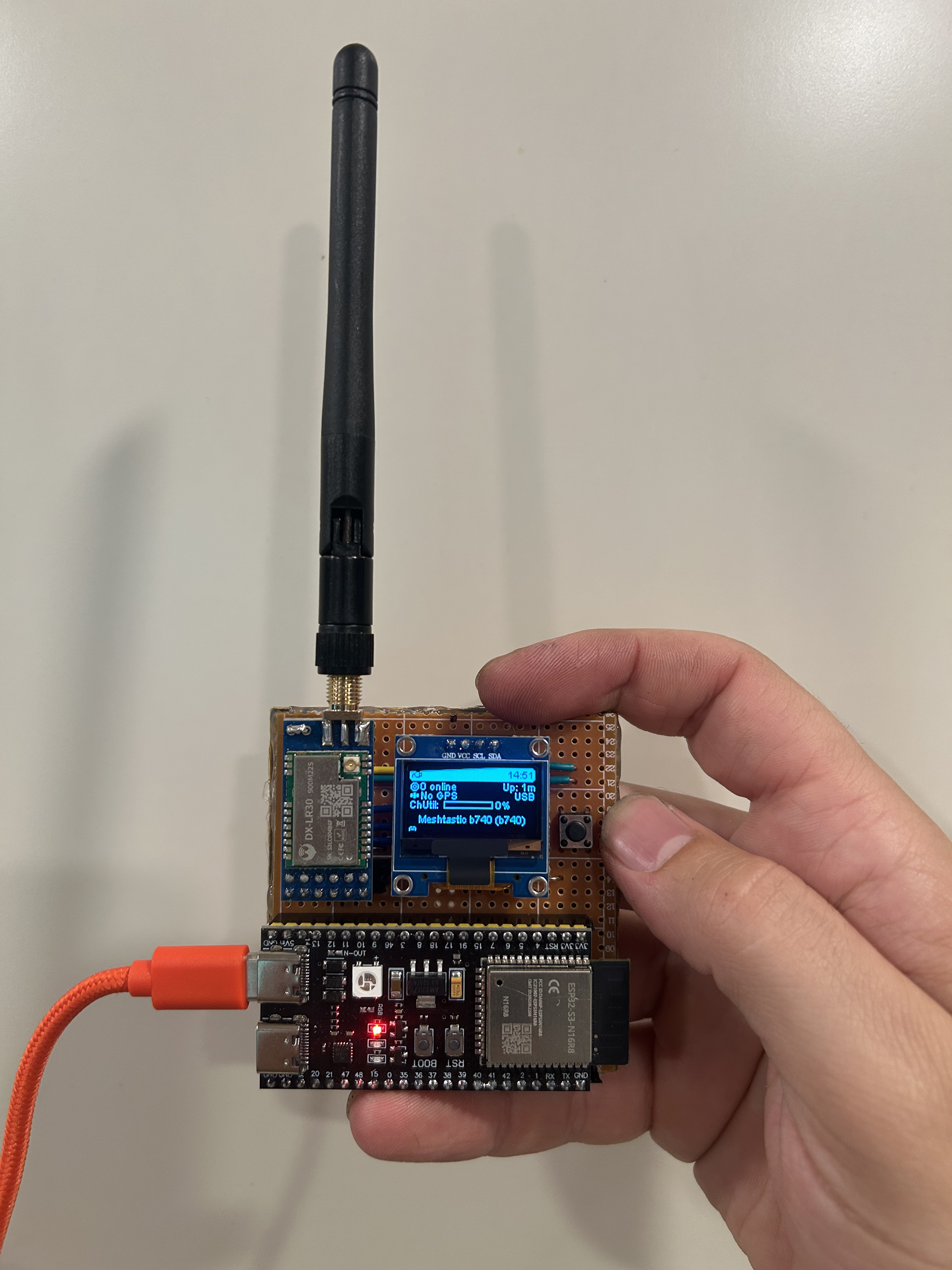
After adding / editing those three files, I was ready to upload the code and debug. After plugging in the ESP32 via USB-C to my computer, I selected the appropriate port in the lower toolbar. Then within the PlatformIO extension menu, I found my custom firmware and clicked “Upload and Monitor.” The build process takes a while, but once complete I saw the Meshtastic welcome screen on the OLED display, yay!
Of course this diddn’t actually work for me the first time, so be ready to debug, check pin connections, and upload a few times before it works!
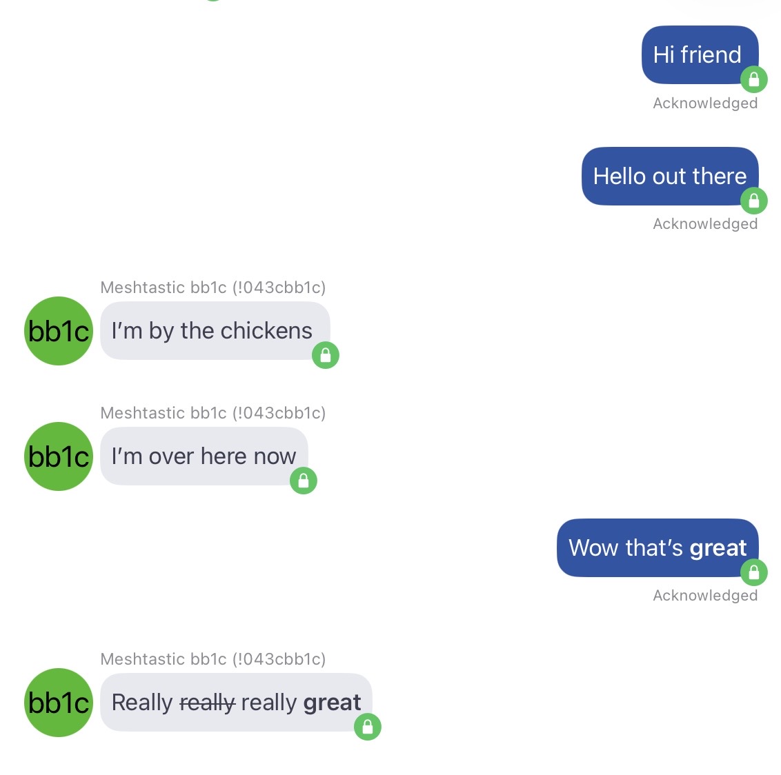
Meshtastic Testing
With my node online, I was ready to test its funcionality using the Heltec V3 kit I got on Amazon as the other node. Both nodes have no keyboard, so will need other peripherals to compose messages. Luckily, Meshtastic provides an awesome app that allows you to connect to the node via Bluetooth, as well as a web client that can connect over HTTPS, Bluetooth, or Serial.
Here’s my testing configuration:
iPhone + Meshtastic App  <--Bluetooth-->  Heltec V3 Node

iPad + Meshtastic App  <--Bluetooth-->  DIY ESP32 Node
After connecting to each node from the respective iOS app, I was sending messages in no time!
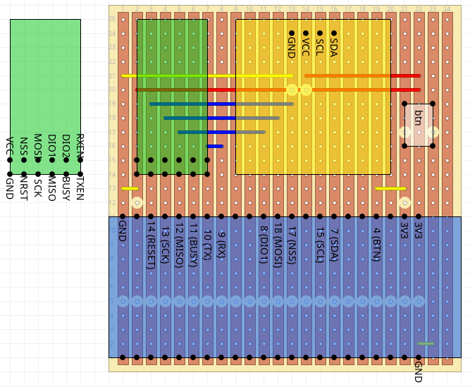
Breadboard to Stripboard
Since the breadboard was a success, I wanted to throw the components on a piece of stripboard and make it more official. In case I ever wanted to tinker with this more, I mounted all three components via female headers, so I can remove those pieces if I need them elsewhere.
Here’s the stripboard layout:
Final Build + Next Steps
I’m honestly a bit surprised that I was able to build this node. Of course a more functional node would include a battery and a 3D printed case, but for now I’m very happy with the results.