DIY Eurorack: Voltage-Controlled Oscilator
The next stop of my DIY Eurorack journey was a VCO. A VCO isn’t required for a modular setup (in fact, nothing is required, that’s kinda the whole point), but I’ve been planning on building out a basic subtractive synth and figure out where to go from there.
The oscilator is where sound traditionally originates in subtractive synthesis, and as you might expect, there are many, many options for professionally (hint: expensive) VCO modules. These modules look really cool, and have lots of crazy features.
For my first attempt at building a VCO, I wanted at least three things:
- 1V/Octave input
- 2+ waveform outputs
- Some degree of fine-tuning the pitch
After quite a bit of digging in the modular DIY communities, I found two designs I liked: one from Sebastian Murgul, and another from Look Mum No Computer. I think Sebastian references LMNC’s design too. These designs use the CEM3340 / AS3340. LMNC’s video about his VCO gives a fun history on the chip, but basically, the IC is built specifically for building VCOs (how nice!), and includes different waveform outputs and 1V/Oct input.
The sourcing of these chips is a little more limited than AliExpress, I found my AS3340 at aisynthesis.com.
Step 1: Schematic
After breadboarding and testing a few things, I started to pick-and-choose different aspects of the two designs I was referencing. The main changes I made were as follows:
- Removed the sine wave. The triangle to sine converter in Sebastian’s design didn’t seem that great (I couldn’t do any better, so I just removed it).
- Instead of having to jacked inputs for hard sync and soft sync, I decided to try one sync input with a toggle switch for hard or soft. Of course now I can only use one sync input, but I think that will be just fine.
Thanks to the AS3340, the schematic is not too complicated.
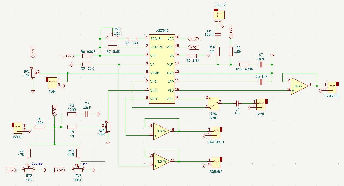
You can find the full KiCad schematic on GitHub (link at bottom).
Step 2: Stripboard Layout
The stripboard layout wasn’t too terrible either. The main annoyance with my current way of doing things is routing all those wires from the front panel to the back. I’d like to find a cleaner way to this at some point.
I knew my toggle switch wasn’t going to fit into my stripboard holes (it has those hefty rectangle leads), plus even if it did, it would sit a lot higher that my pots and jacks. So to fix this, I planned for a section of the stripboard to be removed, and have the switch connect to the panel alone, then just route its wires to the back panel.
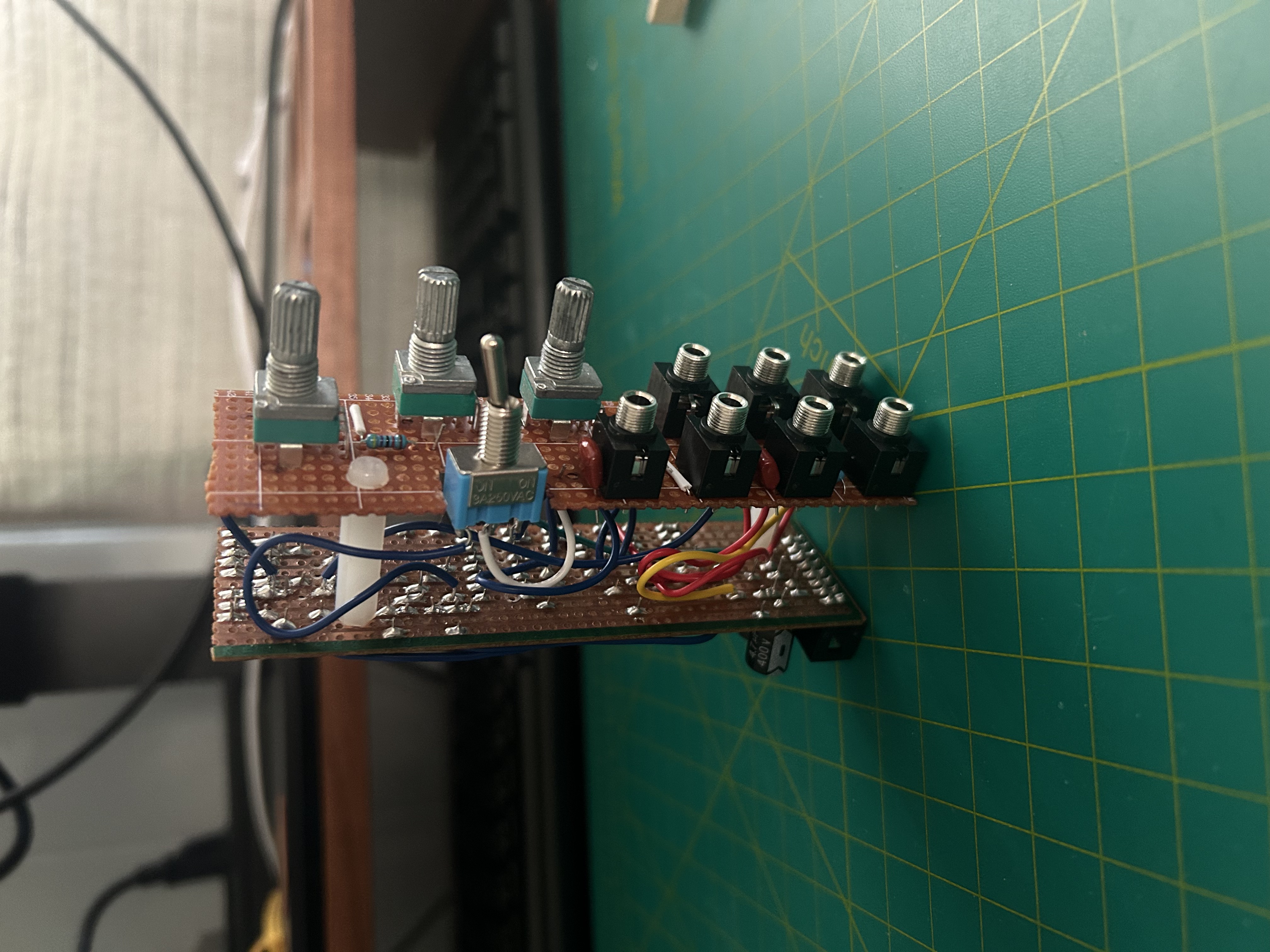
Step 3: Assembly
Time for assembly! Here;s the build before adding the front panel:
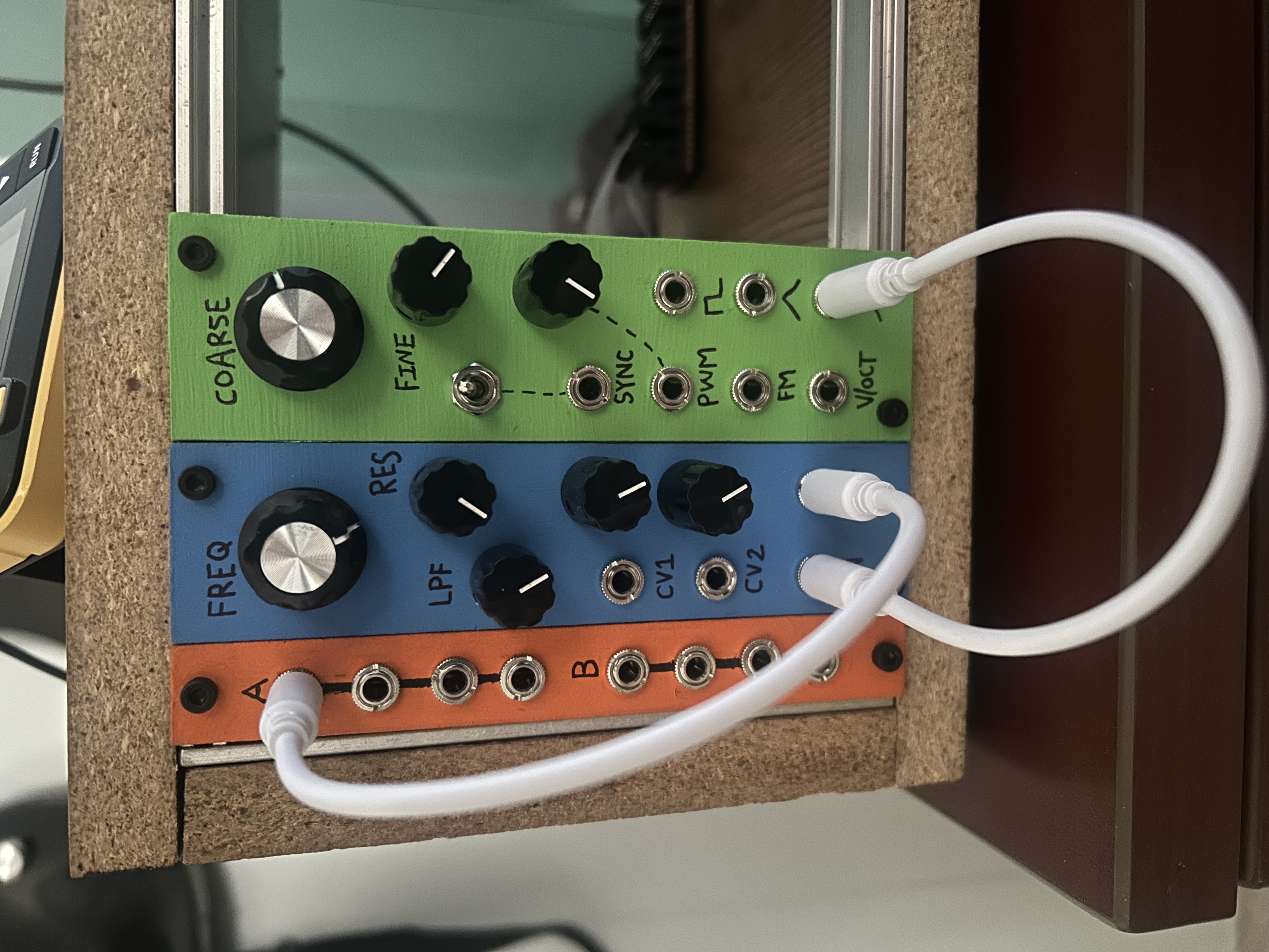
And here’s what it looked like after mounting the panel and adding to my case:
Step 4: Tuning
Once powered on, I needed to tune the VCO. Given this was my first VCO build, I didn’t really understand how tuning a VCO works. My build has two pots, one for course pitch and fine pitch adjustment. I could play a C3 on my KeyStep keyboard (connected via Pitch <-> V/Oct) and turn the knobs til the module gave a C3 pitch, but unfortunately as soon as I played a C4 on the keyboard, I was getting a different pitch from the module.
This is where the trimmers on the back panel come in. They seem to adjust the “spread” of the octave. So in that previous example, after tuning the bottom note to a C3, I would play a C4 on the keyboard. If the resulting pitch from the module was too high (say E4), I would turn the trimmer down to lessen the octave spread. Of course this adjusted the position of the bottom C3, so I would continue this process until I could play a C3 and C4 without making adjustments. Now I could play a C-Major scale and each note sounded great!
Demo
And finally, here’s a quick demo of the VCO:
Specs
Size and Power Consumption
| Attribute | Value |
|---|---|
| HP | 7-ish |
| +12V | 7.5 mA |
| +5V | 1.1 mA |
| -12V | 7.5 mA |
Price
AS3340 (\$12), knobs (\$1), panel (free!), other stuff = about \$18.
Read about how I’m making my panels at the bottom of this post.
Project Files
Checkout the schematic, stripboard layout, and other files here