DIY Eurorack: Voltage-Controlled Filter
Power supply? Check.
Case? Check.
It was time to build a real (sorry, passive multiple) Eurorack module. Many people’s first module is an osciliator (given that’s where a synthesizer’s signal path begins), but I was convinced by strangers on Reddit that a voltage-controlled filter (VCF) is a often an easier place to start.
Step 1: Schematic
A filter is a key part of any synthesizer, so there were a lot of resources out there for DIY VCFs. I came across Benjie Jiao’s Blog and his “MiniVCF” design.
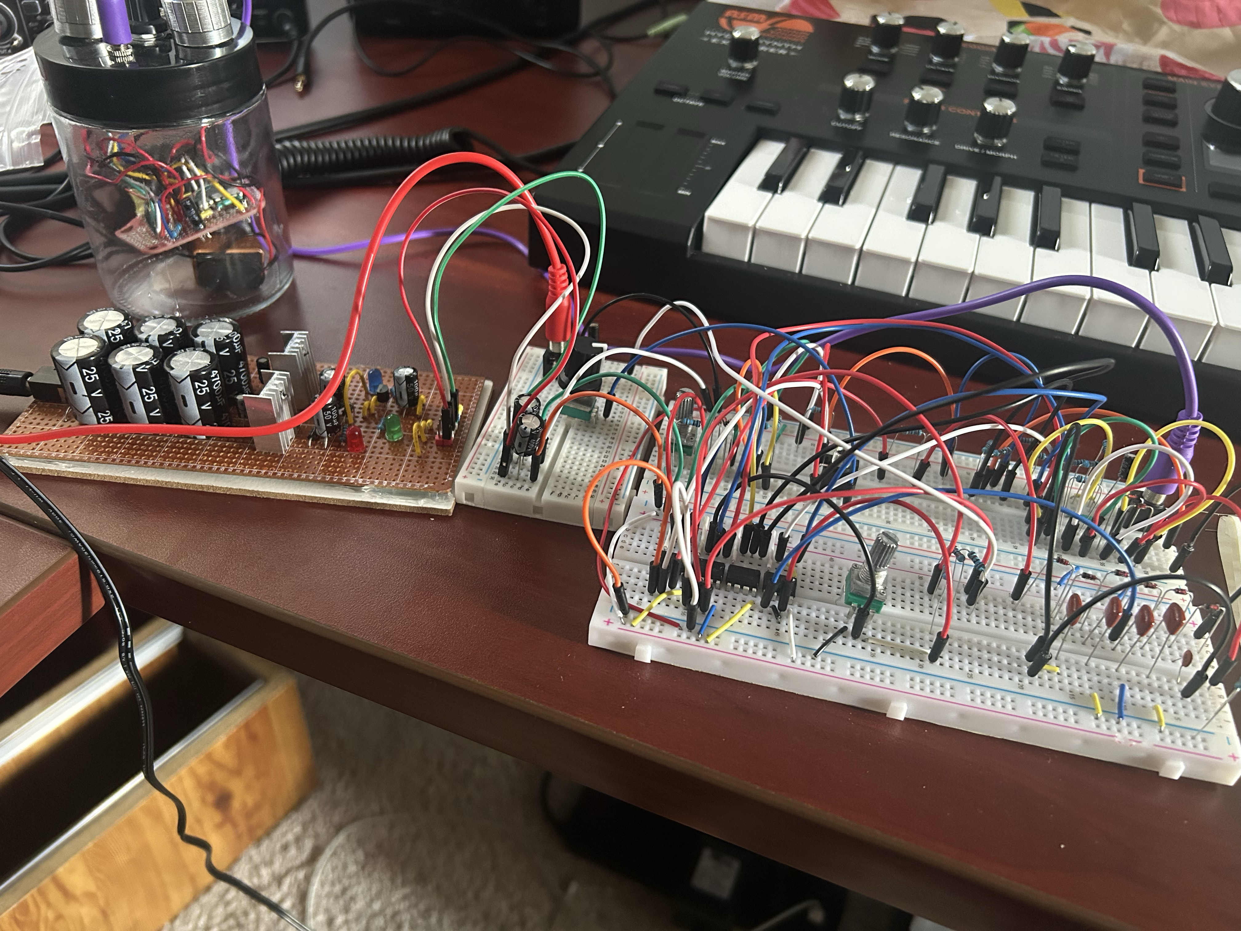
It threw it together on the breadboard, and it worked! Good enough for me for my first build.
I removed a few features of the design (namely the LEDs and the all pass filter selector) to keep things simple and compact (althogh Ben’s design is still smaller than mine, probably thanks to PCBs and more XP). My version of schematic can be found here.
Step 2: Stripboard Layout
I started making my stripboard layout using DIY Layout Creator. While creating my layout, I referenced a phyiscal piece of stripboard (already cut to size) so I could get a better idea of how things would fit together, especially when it came to give the potentiometers and jacks ample space.
I had one small hiccup here that I’ll explain in the next section. Otherwise, this step went smoothly. I prepared for soldering by first drilling trace cuts (and confirming the cuts with a continuity test), as well as trilling thru-holes for my plastic standoffs.
You can find the layout file here.
Step 3: Assembly
I triple-checked each component and location before soldering, and slowly got each part added to the two pieces of stripboard.
Just to be safe, I did a few more continuity tests. To my surprise, some traces I expected to be isolated were conducting electricity. After scratching my head for a good half hour, I realized I missed something very obvious.
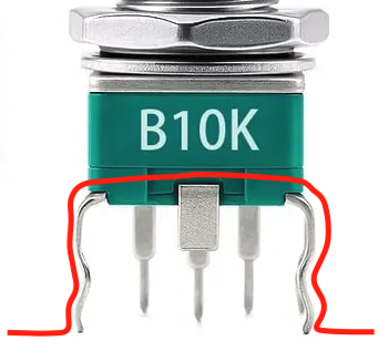
The vertical potentiometers I’m using have hooked legs on two sides. These legs are different from the three leads, and hook into the board adding stability. I didn’t think to check these legs for continuity before, but sure enough, the legs are connected and do conduct electricty.
I added more trace cuts and added extra jumpers to keep things inline with the schematic, but next time I will keep this in mind (and maybe use this to my advantage as a free jumper).
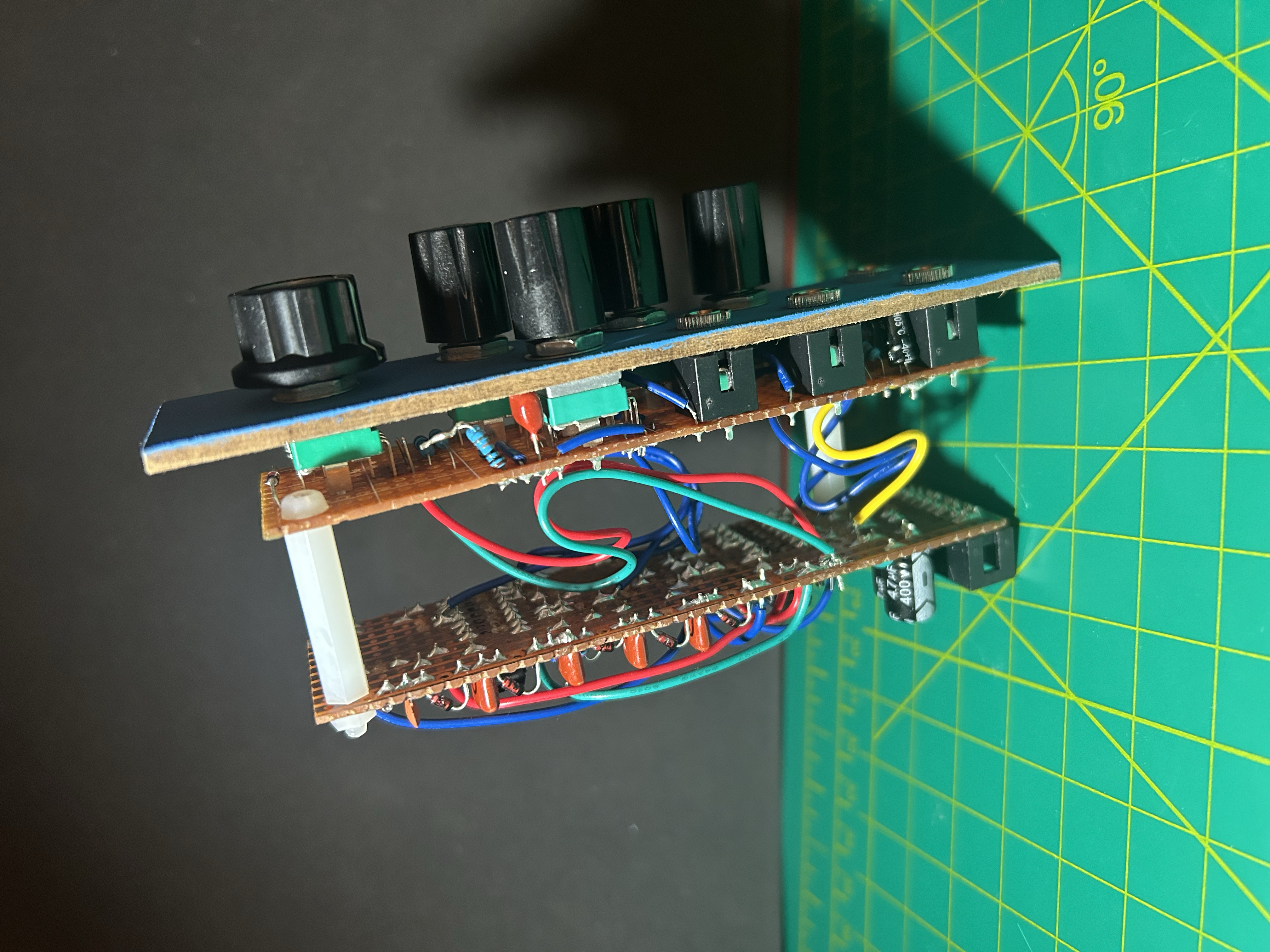
With the two boards finished, the last soldering step was to add the wire connections bewteen the two. I’ve seen others use male + female pins to accomplish this interface, and I might try that approach on a future design. But for this module the 8 or so wires I connected wasn’t too much of a pain.
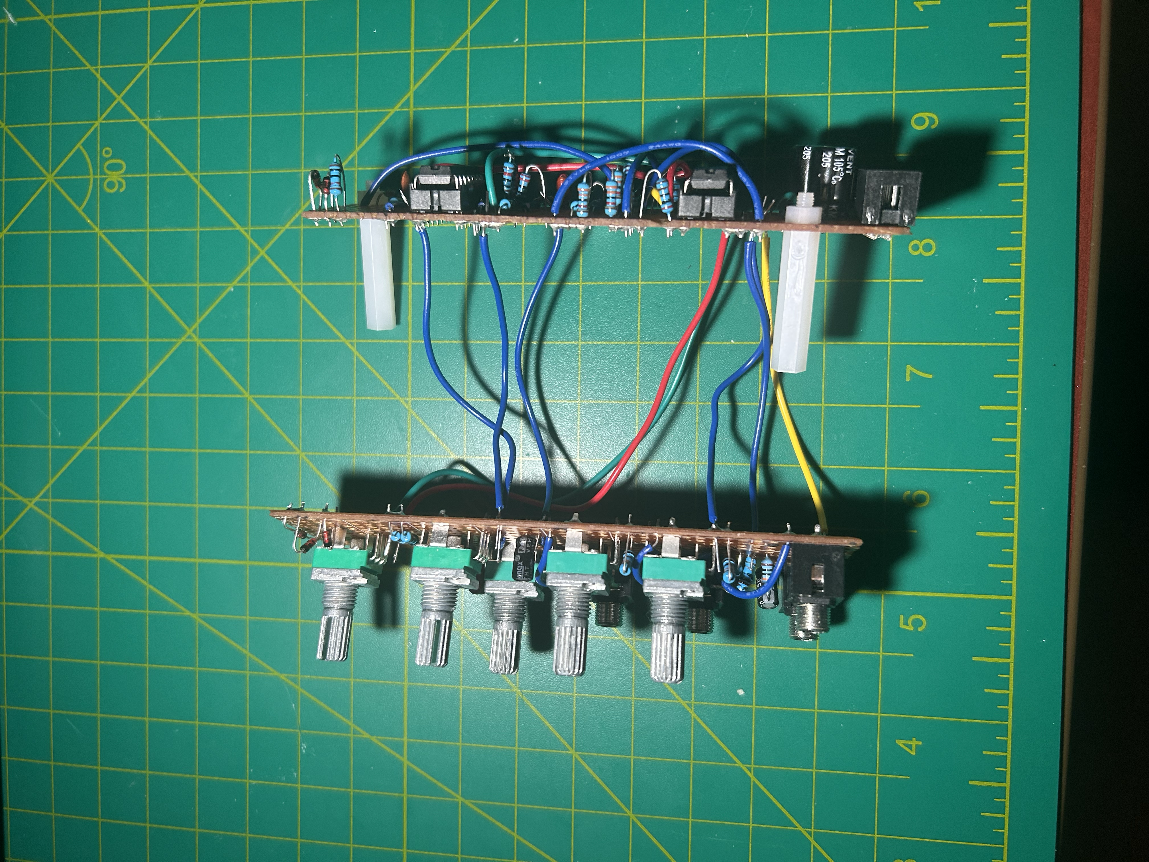
I bent the wires a bit to clear the space, and attached the standoffs on the other board.
Step 4: Front Panel
In my previous post where I built a passive multiple, I discuss how I’m building front panels with free craft wood from Home Depot’s Kid Workshops.
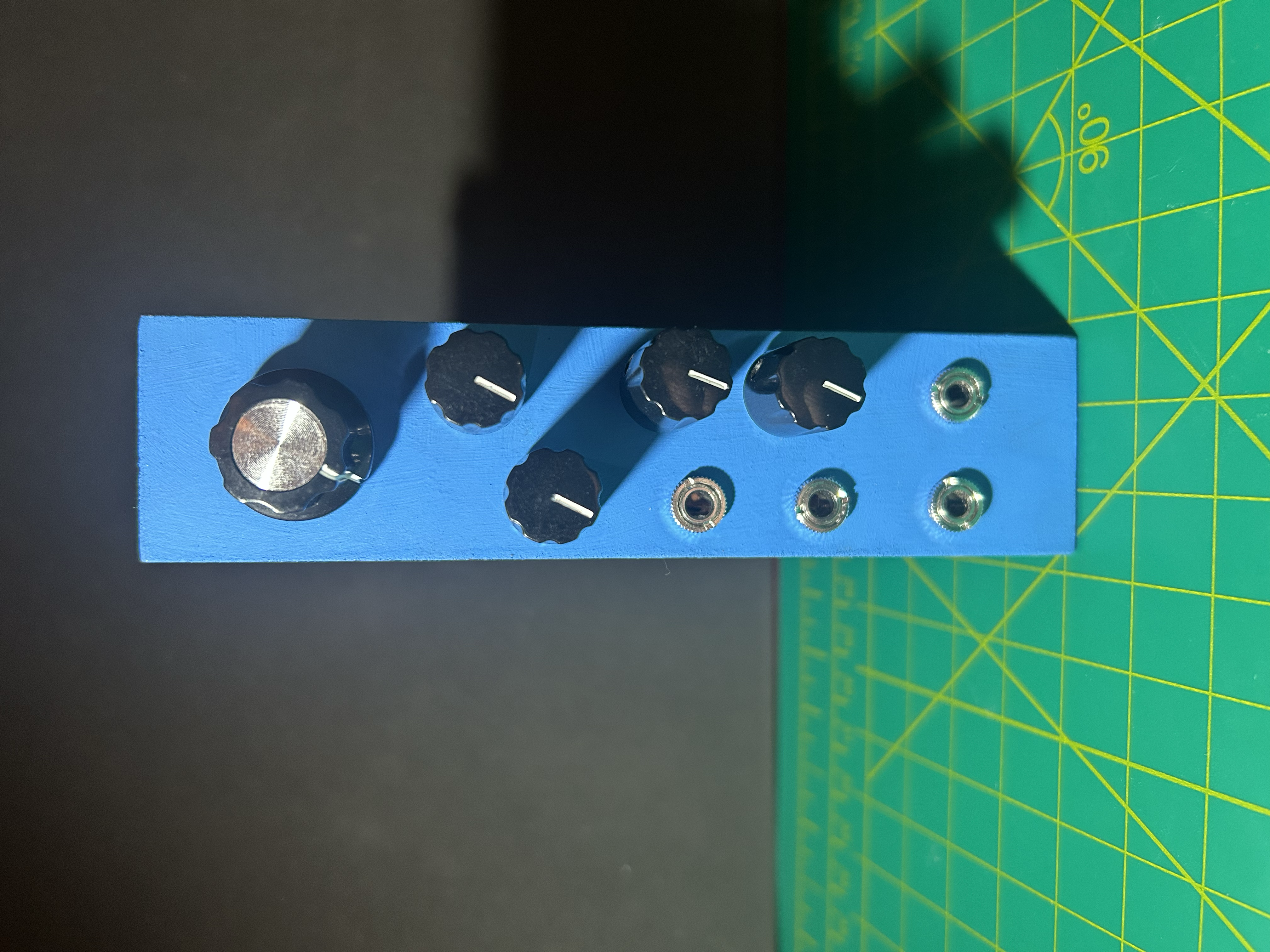
I cut a 6-ish HP piece of wood and started drilling some holes. I added a splash of blue paint, squeezed the interfaces thru the holes, and attached the nuts and knobs.
I’m debating if I should add labels to the knobs and jacks, but for now I like the simple look.
Demo
I gave it a quick test using an Atari Punk Console as my oscililator, and I was able to filter sounds!
Specs
Size and Power Consumption
| Attribute | Value |
|---|---|
| HP | 6-ish |
| +12V | 5 mA |
| +5V | 0 mA |
| -12V | 5 mA |
Price
Pots (\$2), knobs (\$2), panel (free!), other stuff = about \$7.
Read about how I’m making my panels at the bottom of this post.
Project Files
Checkout the schematic, stripboard layout, and other files here