DIY Eurorack: Passive Attenuator
While playing around with my new LFO module, I started learning about the concept of attenuation. Depending on the specs of your modules, it is sometimes necessary to lessen the strength of a signal. In my case, I was interested to see how an attenuator could help me fine-tune the modulation of the FM input on my VCO, plus making a “passive attenuator” is super simple and sounded like a relaxing project.
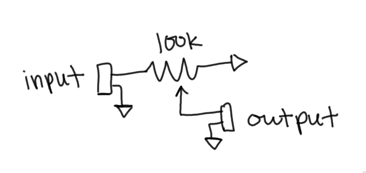
Schematic
The concept of the attenuator (and the schematic itself) is pretty simply. The signal comes into a variable resistor, which limits how much of that signal goes out to the other side.
The poteniometer can be setup so either 100% (full turn CW) is full attenuation or no attenuation. From what I’ve seen online, it’s more intuitive for 100% to be no attenuation, cause that feels more like a volume knob interface.
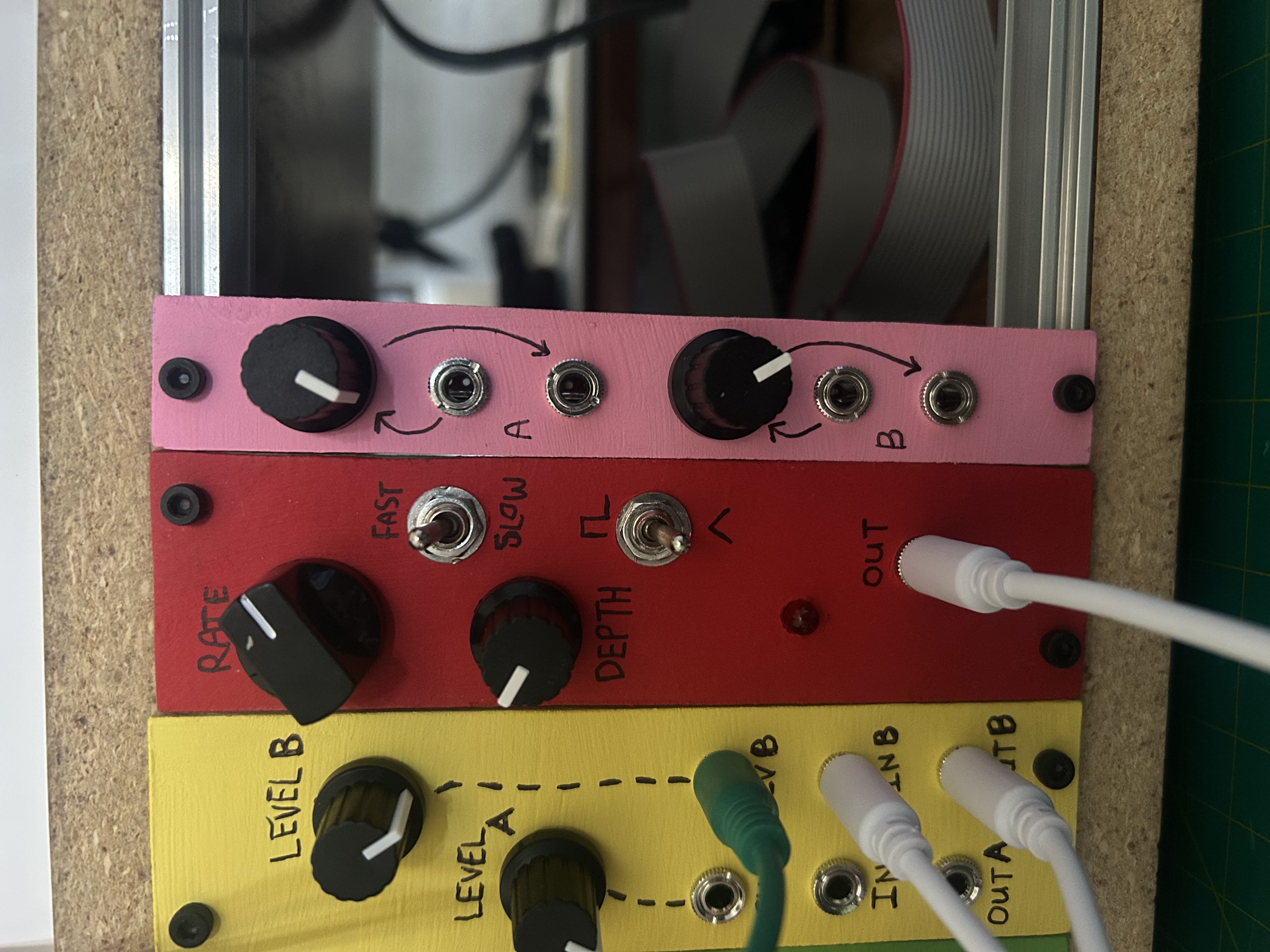
Done!
Specs
Size and Power Consumption
| Attribute | Value |
|---|---|
| HP | 4-ish |
| +12V | 0 mA |
| +5V | 0 mA |
| -12V | 0 mA |
Price
Knobs and pots (\$0.5), jacks (\$0.5), panel (free!) = about \$1.
Read about how I’m making my panels at the bottom of this post.