DIY Eurorack: Dual Power Supply
Building a PSU seemed to be a logical place to begin my DIY Eurorack journey. I wouldn’t get very far with prototyping modules without the +12V/-12V/+5V power supply required by most designs.
Of course there are several professionally designed and built Eurorack PSUs, but I’m hoping to build (most) everything from scratch as I explore Eurorack. This will keep things educational and much, much cheaper.
Background
I’m still fairly new to electronics, so I relied on some great resources out there that explained how to build a DIY PSU. The first of which was a video by Moritz Klein. The video does an awesome job of explaining the PSU design step-by-step. Here’s the basics:
- We can use an AC supply (via AC-AC wallwart) and diodes to get positive, neutral (GND), and negative voltage levels
- Large capacitors in parallel can clean the (now) DC voltage
- Voltage regulators can be used step-down the incoming voltage to 12V and 5V
I also (heavily) borrowed ideas from a DIY kit from Frequency Central. I watched a few videos where this kit was recommended, but I didn’t want to pay the PCB price (and shipping), so I studied the image of the PCB and (hopefully) worked out the underlying schematic that I could use on a stripboard.
Schematic
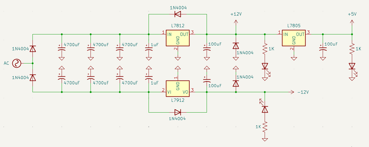
Using KiCad, here’s the schematic I came up with. I think it’s pretty close to the one used in the FC Power PCB:
Breadboard Testing
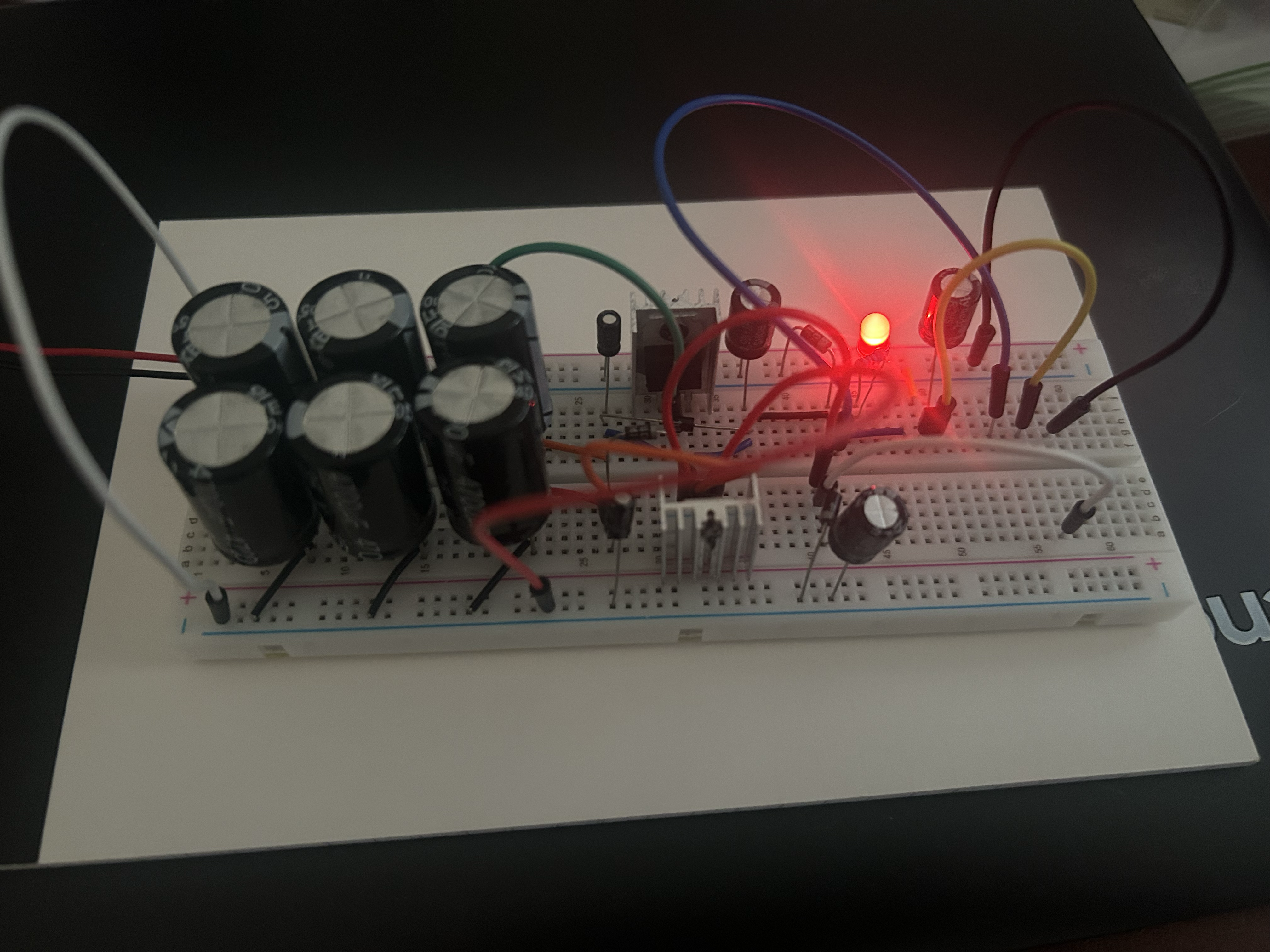
I ordered a few parts that I was missing (mainly the big caps, voltage regulators, and heatsinks), and testing things out on a breadboard. I also picked up a 120VAC-to-12VAC wallwart on Amazon. I was careful of the polarities of my capacitors, but just to be safe, I covered the circuit with a wooden box before turning it on. Nothing blew up, hooray! I used my multimeter and confirmed I had +12V, -12V, and +5V.
Stripboard Planning
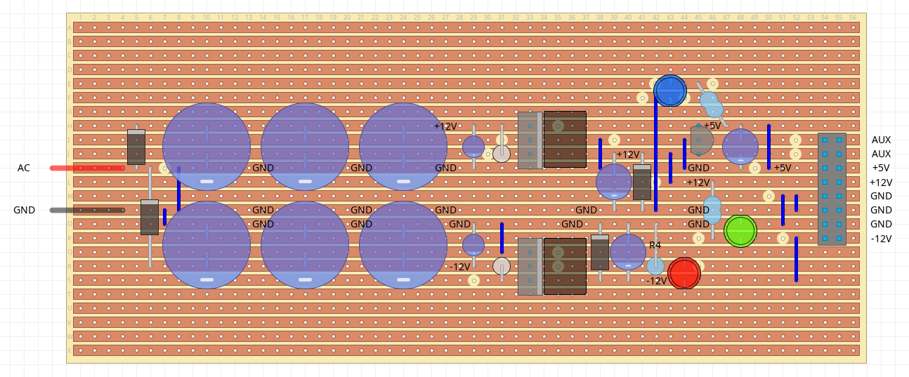
As I said earlier, I decided to save some money and not buy the FC Power PCB, and instead rely on the schematic I inferred from that PCB and some stripboard I had on hand. I used DIY Layout Creator to create the stripboard layout. This was super helpful, cause even this small PSU had some complexities that went beyond planning things out on paper. This was also my first time creating a stripboard layout, so I’m sure there’s some room for improvement.
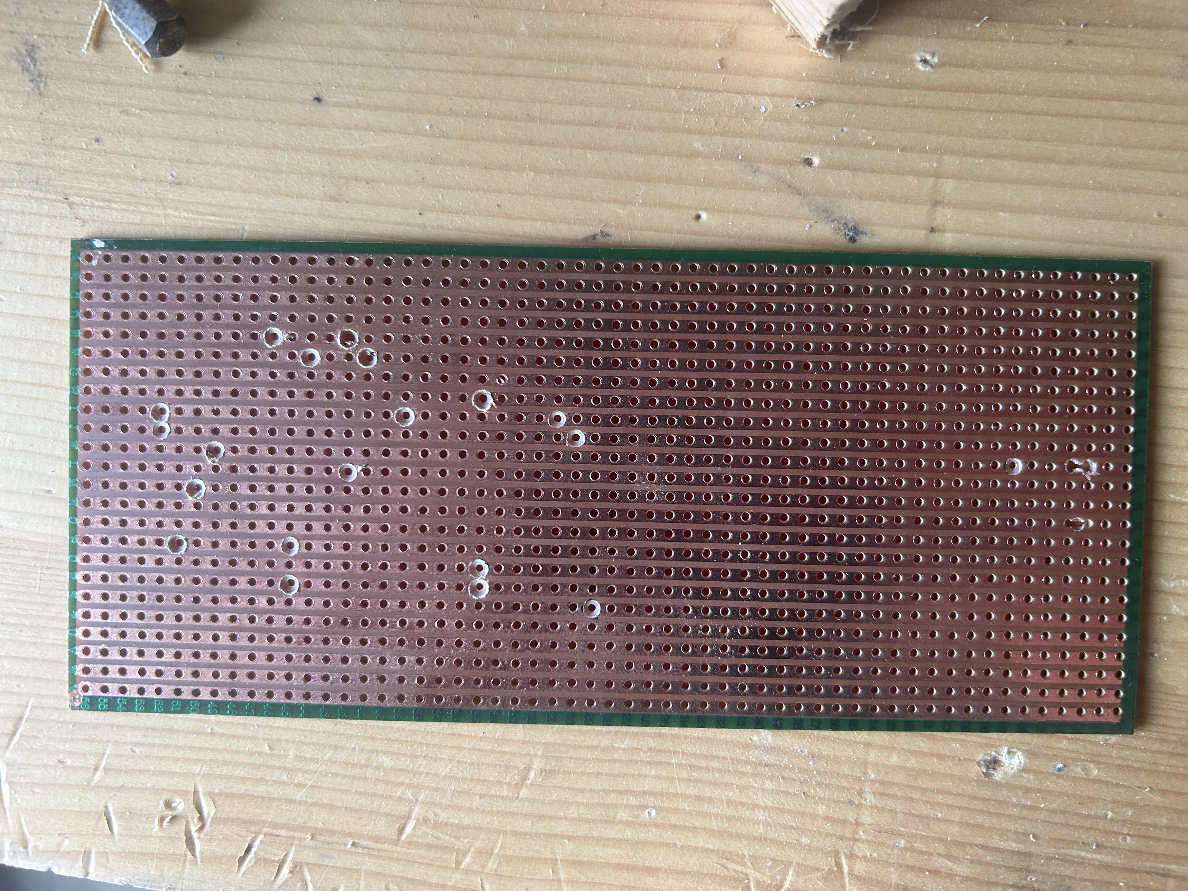
After I finished my layout, I marked my trace cuts with a marker, and drilled them out. I’ve seen people do this by hand with a drill bit, but I was unable to make substantial progress this way, so I used my drill. After drilling, I used my multimeter’s continuity test mode to ensure that there was no connection between the traces.
My power socket leads didn’t fit my stripboard, so I also had to use a smaller drill bit and a knife to create a slot between two of the stripboard holes.
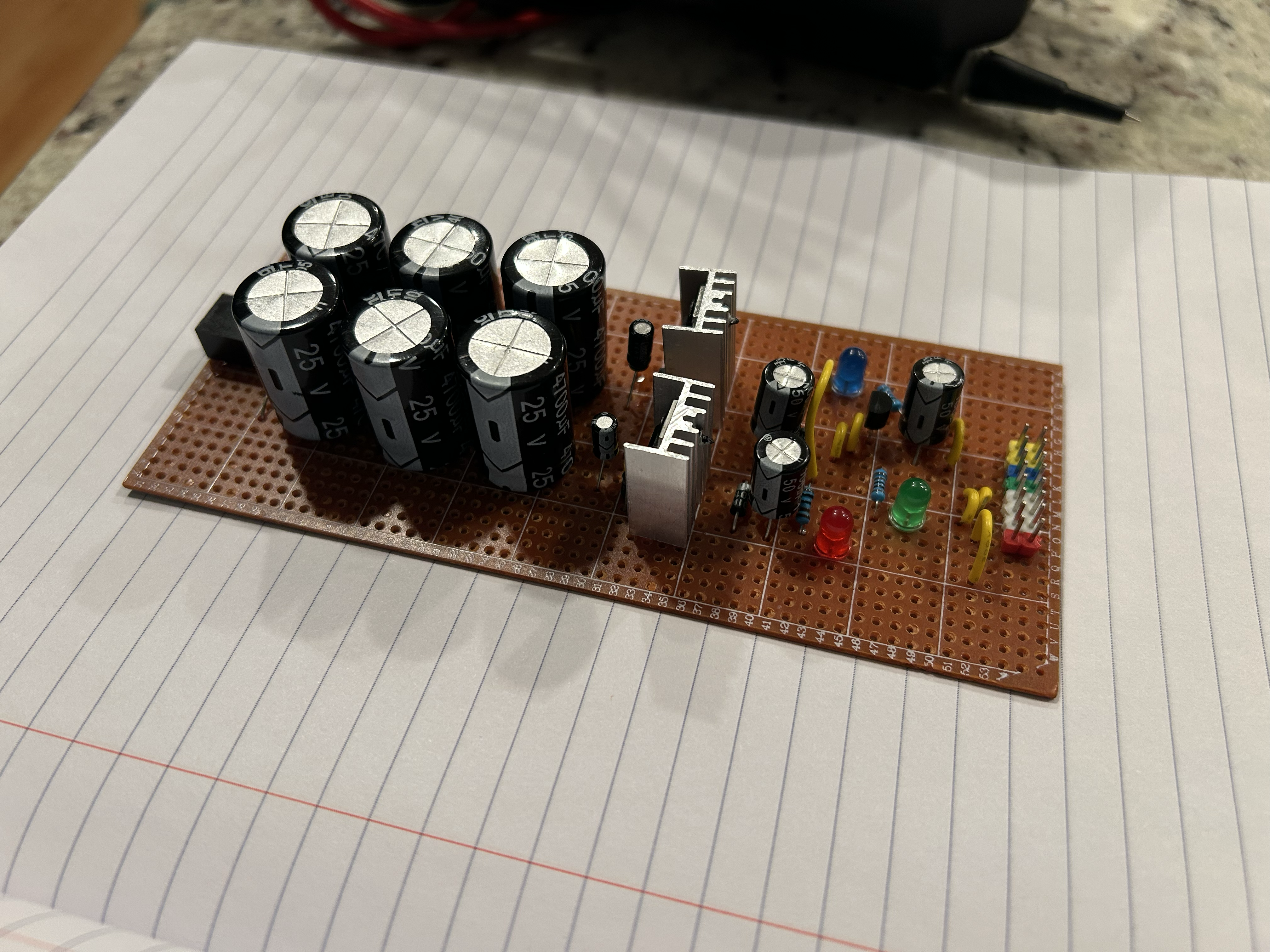
Assembly
I was ready to add components. I double-checked my layout each time I added a component to avoid any desoldering (which is always a pain), and worked my way thru the diodes, resistors, and other components. I had a few different colors of pin headers, so I used the following color scheme for the output headers:
- Red: -12V
- White: GND
- Green: +12V
- Blue: +5V
- Yellow: Aux (CV, Gate)
These colors correspond to the LEDs that indicate if that power source is working correctly.
Once done, I plugged things in (first covered to avoid any exploding caps) and measured the pin voltages. There was a little smoke at first, but it dissipated and hasn’t come back, so I don’t know what that was about. For now it seems to be working, so I’m calling this project COMPLETE!
As suggested by others, this design might not be the best fit for a large Eurorack system, but can be a used as a bench power supply for testing modules. Depending on where my Eurorack journey takes me, I can see myself using this PSU for either use case.
Specs and Price
Power Output
From what I can tell, calculating a power supply’s output potential is tricky, it requires a fancy tool or smart maths. I don’t have either, so I’m relying on the specs proivded on the FC Power page.
| Attribute | Value |
|---|---|
| +12V | 500 mA |
| +5V | 100 mA |
| -12V | 500 mA |
Price
Big caps (\$2), regulators (\$1), other stuff = about \$4.
Project Files
Checkout the schematic, stripboard layout, and other files here