DIY Eurorack: 3-Channel Mixer
When organizing my box of components, I found a handful of ~75mm faders. Faders are variable resistors similar to potentiometers, but instead of turning a knob, you slide a little thingy up and down. I didn’t really care what module I was going to make next, I just wanted to make something with faders. After a few minutes of brainstorming I decided to make a mixer.
Schematic
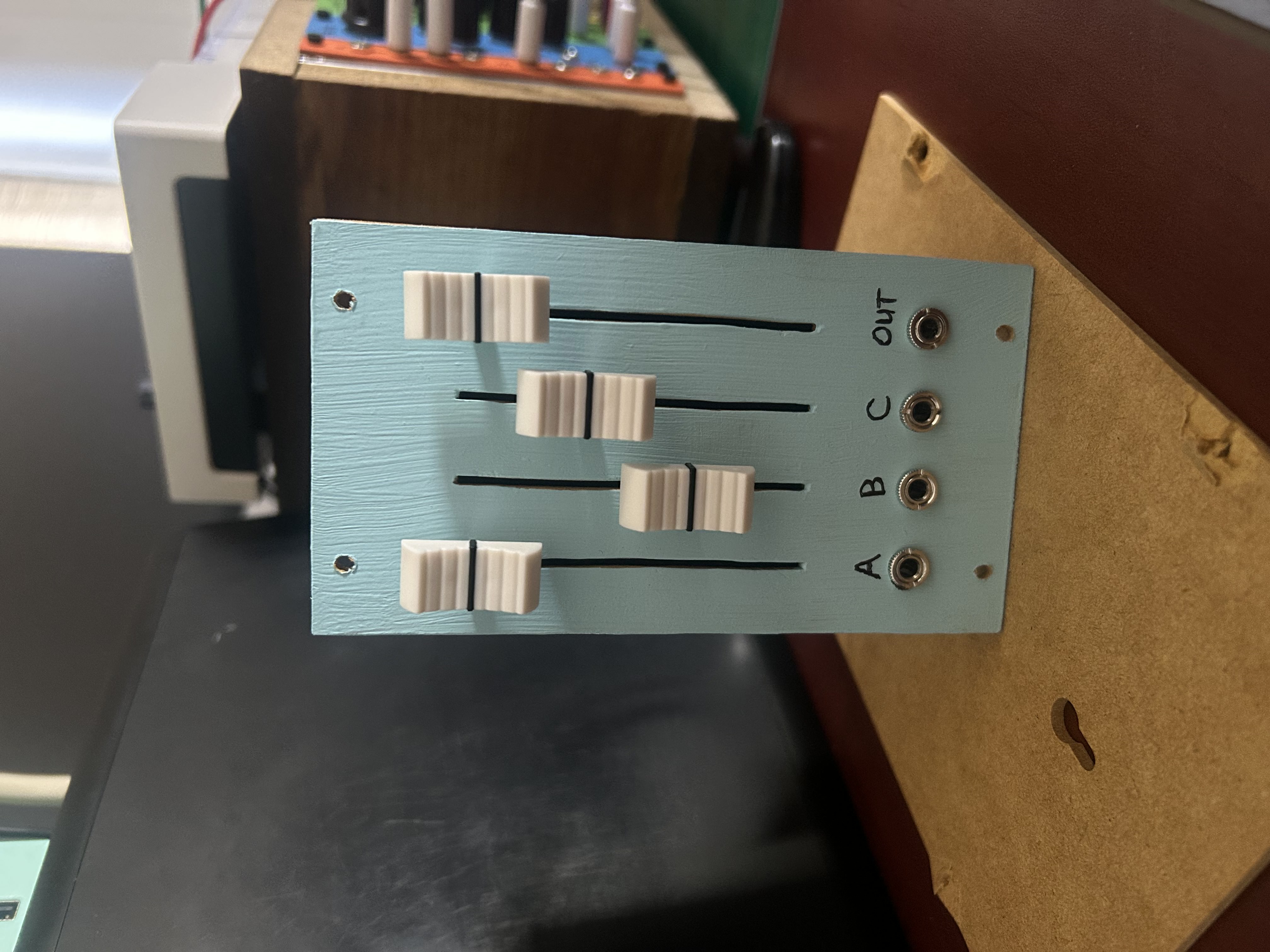
I started with a passive mixer (not powered), and quickly hit the limitations of passive mixing and reworked the design to use my +12V/-12V power supply with a TL072 to sum and buffer the inputs. Overall there’s nothing crazy going on here. Input levels are adjusted by their respective fader, the inputs are summed and buffered, then I use a final buffer to control the level of the output. I could have done 4 inputs with one output, but I like the symmetry of 4 jacks + 4 faders.
Stripboard Layout
Since this was my first time using these faders, I had no clue what pins did what. I got a bit of guidance on the internet, and used my multimeter to confirm.
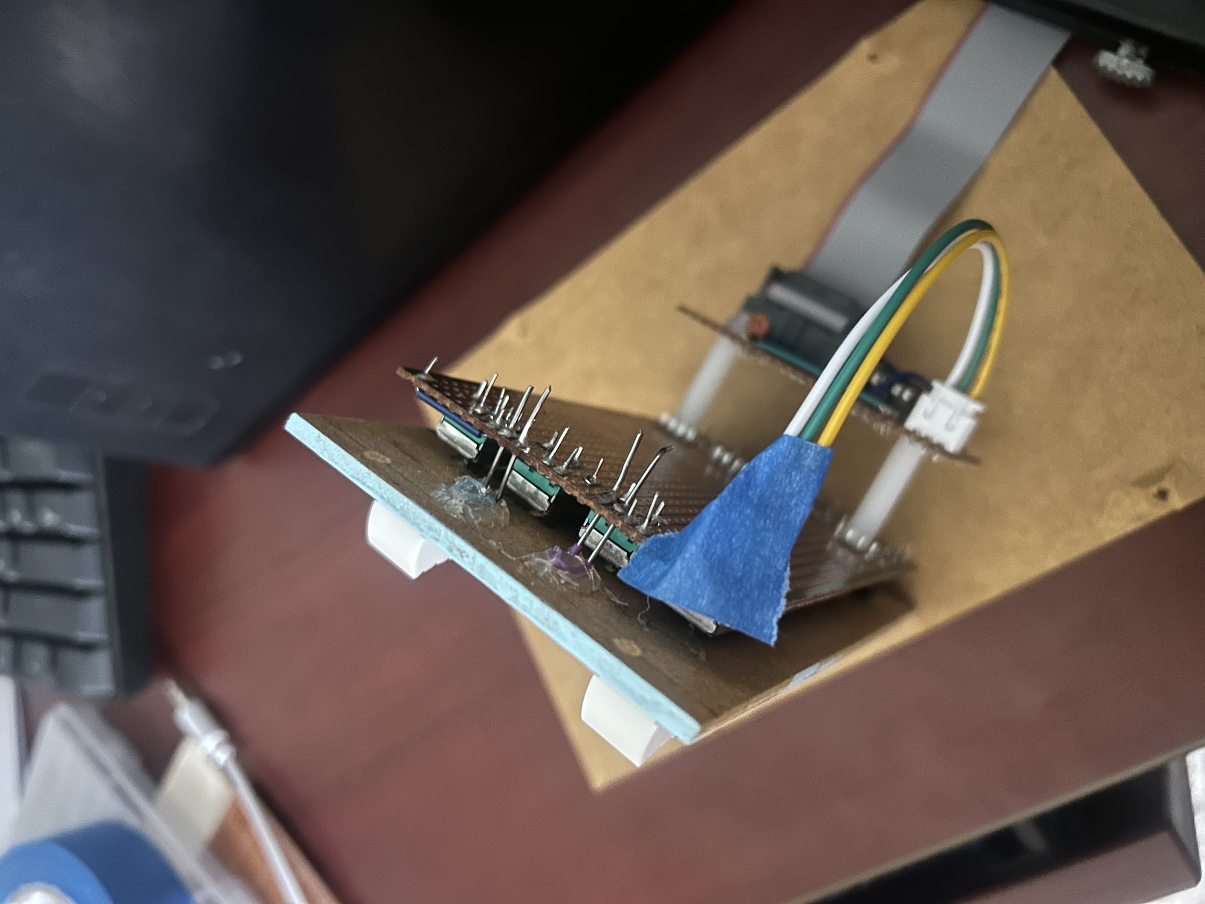
My stripboard piece (56 holes x 24) perfectly fit 4 faders. For other modules, I’ve cut the stripboard to be 42 holes high and then adjust the width as necessary. Given the simple design, I didn’t need to match the entire back panel with a new piece of board, so instead I used the left over 24 x 14 piece for my op-amp and power connection.
Since I was already experimenting quite a bit with this module, I also tried to solve a frustration I’ve had with previous builds: wiring between my two boards. I usually need to connect 5-10 wires between my boards, which involves soldering to the copper side of the stripboard. That’s not a huge deal with one wire, but as I had wires it gets really cramped, and then I get nervous when folding these wires to connect the two boards. I looked up wire connectors on AliExpress and found a JST connector kit with several sizes. Because the mixer was pretty simple, I only had 3 wires to route, in my stripboard layout I made sure to have these three connections next to each other so the wire connector would work.
Assembly
Assembling the mixer was a bit trickier than other builds, but it presented a fun challenge. After soldering and cutting my wood panel to size, I had to cut slots for the faders. For potentiometers, jacks, and other circular components, I can just drill a hole. Luckily, with a few tests I found the blade of my jigsaw had a good width to fit the faders. The jigsaw would destroy the board pretty quickly, so I used the blade by hand. Very tedious, but it worked! Well sorta, some slots are a bit jagged but that’s okay.
At the last moment, I realized another issue: the faders aren’t actually mounted to the front panel, and instead just sit on the board and poke thru. So unlike a potentiometer that has an outer nut, if too much pressure is placed on the faders, they will sink into the front panel, slightly hinging down to where the jacks are connected below.
Solution? Paper clips and hot glue! I folded a paperclip so that a portion of it could be glued to the back of the front panel, and then the ends of the clip could feed thru the stripboard and soldered in. This essentially connects the stripboard and the front panel enough to resist a bit of pressure. My first attempt (shown in the picture) blocked the rails of my case, so I ended up ripping those out and mounting a single clip lower on the board, but that’s the basic idea.
After that, it was just a matter of paint and labeling. My JST connectors were handy during the assembly as I had to debug an issue on the back board, so I’m definitely going to try that again for future builds. As for faders? They are a fun addition to my Eurorack build, but I’ll probably stick with potentiometers for my next project.
Specs
Size and Power Consumption
| Attribute | Value |
|---|---|
| HP | 14-ish |
| +12V | 1.2 mA |
| +5V | 0 mA |
| -12V | 2.4 mA |
Price
Faders (\$1), jacks (\$0.5), other stuff (\$2?), panel (free!) = about \$4.
Read about how I’m making my panels at the bottom of this post.