Chimera: A DIY Multi-Effect Guitar Pedal (Part 2)
In the previous post, I assembled the hardware for my DIY guitar pedal. As opposed to an analog device which solely relies on electronic components to process audio signals, this pedal is digital (thanks to the Daisy Seed microcontroller). This means my project was from over, I still needed to program the digital sound processing and component interfaces.
Toolchain Setup
Before getting to this point, I had tested the Daisy Seed quite a bit on a breadboard, which means I had already installed the compiler toolchain, etc. I won’t cover any of that here, since it is well documented on the Daisy Seed Wiki.
Conceptual Design
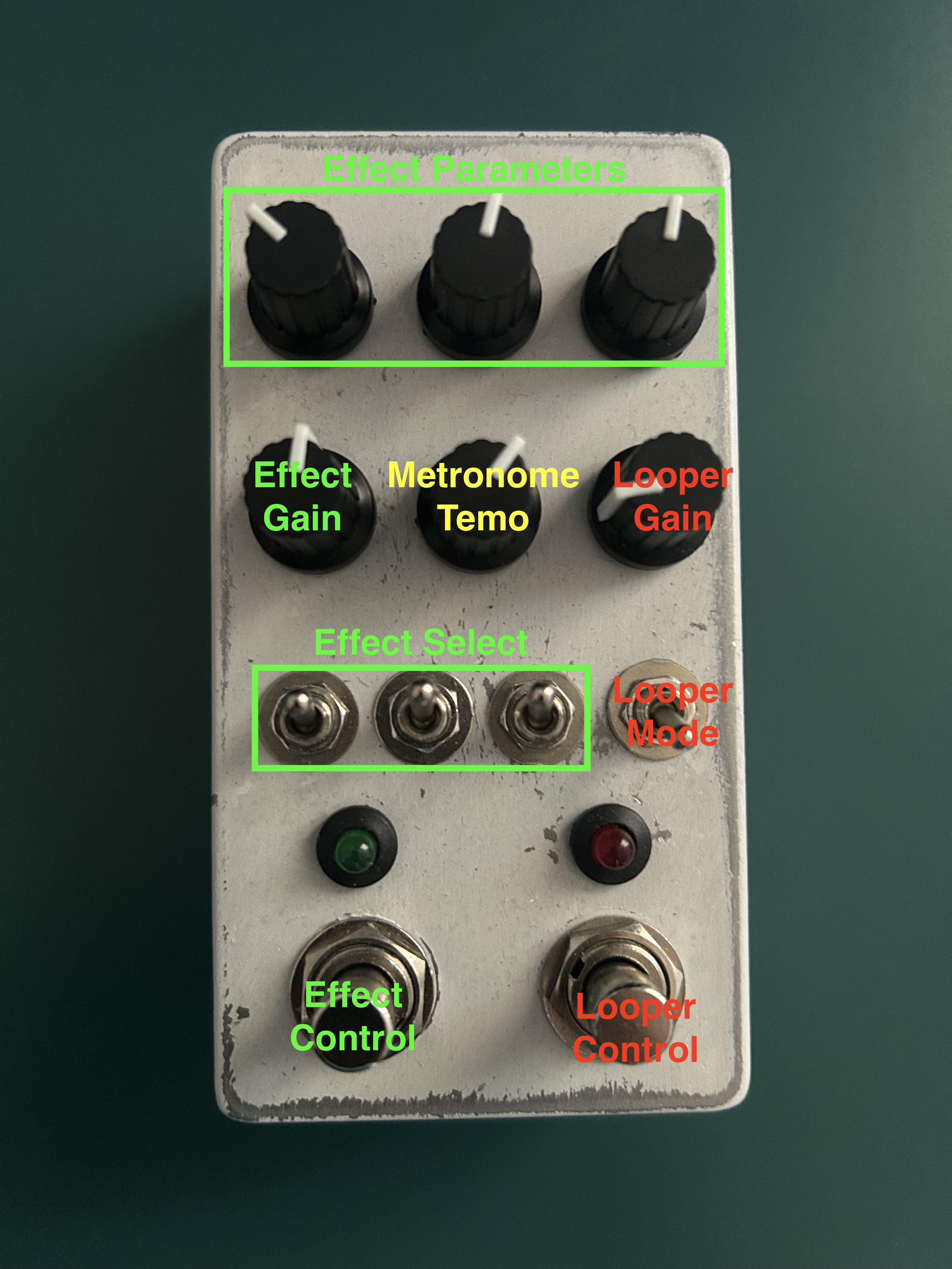
The Terrarium PCB has 6 poteniometers, 4 switches, and 2 footswitches (each with an accompanying LED). The functionality of the pedal was entirely up to my code, so I started brainstorming. After a fair amount of doodling designs on paper, here’s what I came up with:
- Use 3 switches to select an effect, allowing for 8 effects ($ 2^3 = 8 $).
- Multiple effects can be used at once, with each effect being selected with the left footswitch.
- The top 3 pots control the different effect params, while the 4th pot controls the gain for that effect.
- One of the effects will be a metronome / kick drum, so the 5th knob acts as a dedicated tempo control.
- The right footswitch controls the looper.
- The last toggle switch can select bewteen 2 different looper modes provided in the DaisySP looper module.
Here’s a quick summary:
Effects
Since this was my first time writing DSP code, I decided to keep things simple and rely on the prebuilt DSP modules provided in the DaisySP library.
Here’s the effects I settled on:
- Chorus
- Overdrive
- Delay
- Tremolo
- Flanger
- Autowah
- 4-band equalizer
- Metronome / kick drum
Parameter Locking + ADC “Wiggle”
The effects were straightforward (since I borrowed from DaisySP), and the looper function was easy too (since I borrowed from someone on GitHub (I’ll add the link if I can find it again)).
The only tricky part was something I called “parameter lock” (I bet there is a real name for this out there). Here’s the problem, let’s say I have the Chorus effect active with param1 = 0.5. Then I toggle a switch, activate the Overdrive effect, and start adjusting the potentiometer so that param1 = 0.3. If I toggle back to Chorus, I don’t want it to update the parameter 1 value with the current poteniometer position, rather, it should keep the value that was set previously until the user move the potentiometer.
Locking the parameter values wasn’t too tricky, but deciding when to “listen” to the poteniometer position again stumped me for a while. I learned the trial-and-error that the analog-to-digital converter (ADC) isn’t perfect. When the potentiometer was sitting still, there was some variance in the readings. There might be a fancy name for this, but I called it the “wiggle”. Knowing this, I simply checked if the difference of the previous and new value, and see if that was greater than the wiggle threshold.
Here’s and example of how that looked in the Chorus effect:
case CHORUS:
    if (fabs(q1 - p1) > pq_wiggle) chorus.SetLfoDepth(p1);
    if (fabs(q2 - p2) > pq_wiggle) chorus.SetLfoFreq(p2 * 2.0f);
    if (fabs(q3 - p3) > pq_wiggle) chorus.SetDelay(p3);
Putting it All Together
With the ADC wiggle handled, it was just a matter of adding all the effects together, and playing around with values a bit. It’s far from perfect, but I’m happy with the results.
Here’s a short demo on YouTube.
Code
You can also check out the (poorly written) code here.