Chimera: A DIY Multi-Effect Guitar Pedal (Part 1)
While researching audio buffer designs to use with my Daisy Seed microcontroller, I came across Terrarium, a PCB specifically designed for building an effects pedal with Daisy. I wasn’t planning on building a guitar pedal, but it sounded like a fun project.
PedalPCB provides detailed build documentation, including a full schematic, parts list, and a drilling template for the 125B enclosure. I was going to build the schematic on stripboard and add some customizations (like a OLED screen and a rotary encoder), but I decided against getting too crazy for my first guitar pedal build. So instead I ordered the PCB and (for the most part) built the pedal as laid out in the documentation.
Step 1: Gather the Parts
Aside from the Daisy Seed, I ordered everything thru AliExpress, including the 125B enclosure.
The only thing that was somewhat tricky to find was the 16mm right-angle potentiometers. I had some right-angle pots on hand, but they weren’t the right size for the PCB. I accidentally ordered pots with a built-in switch (the pot clicks when I turn it all the way to the right). There were two metal contacts at the bottom which I assumed is for the switch. I cut these off with pliers and covered the bottom with masking tape to prevent any interference. Kinda hacky but it works.
Before getting ahead of myself, I tested the basics of this setup on the breadboard. I’ve played around with the Daisy previously, so I was already familiar with the basics, but I was curious to test the voltage regulator and op amp circuitry.
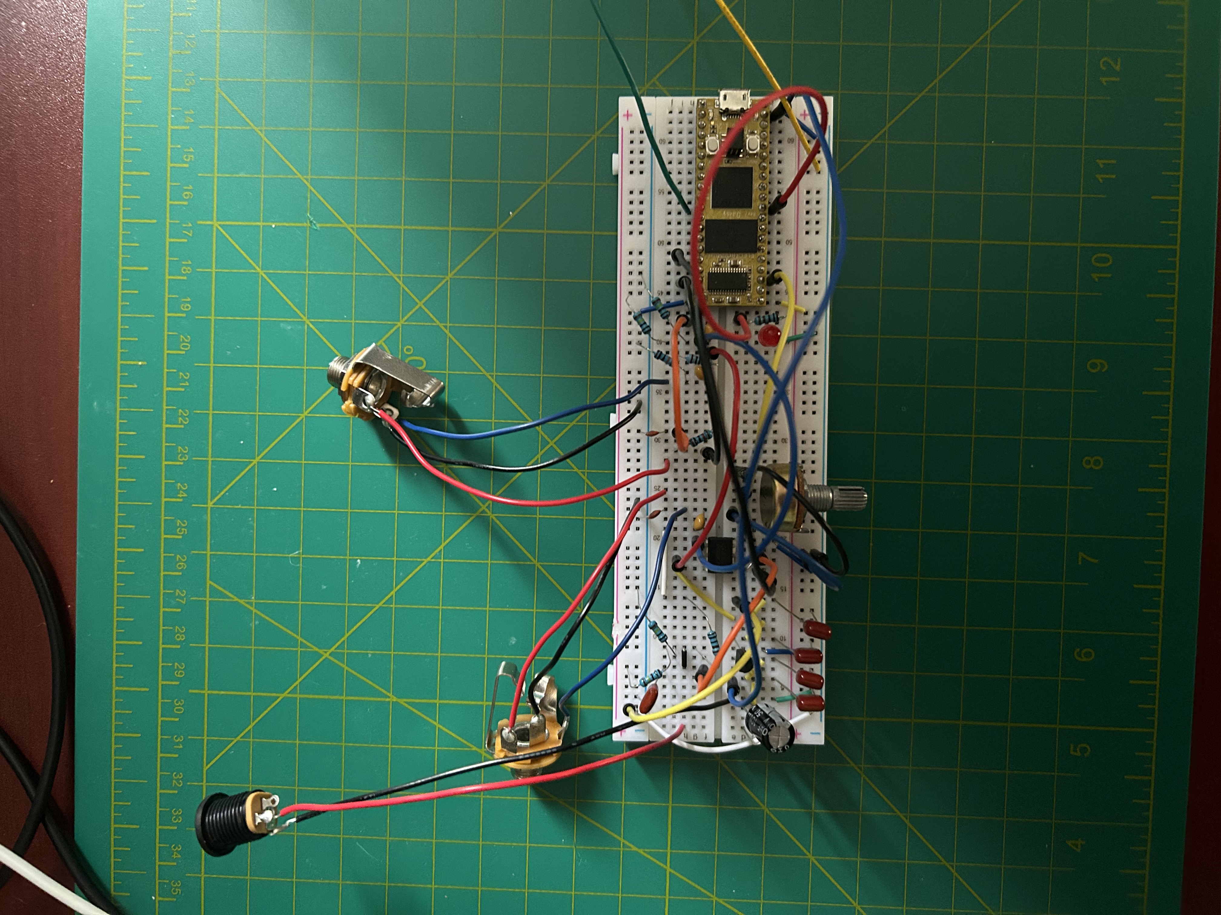
I tested a simple Chorus effect, and it worked great. Time to get this off the breadboard!
Step 2: Build the Enclosure
Building the enclosure was pretty fun. I printed the drill guide from the Terrarium build docs, and taped that onto the enclosure.
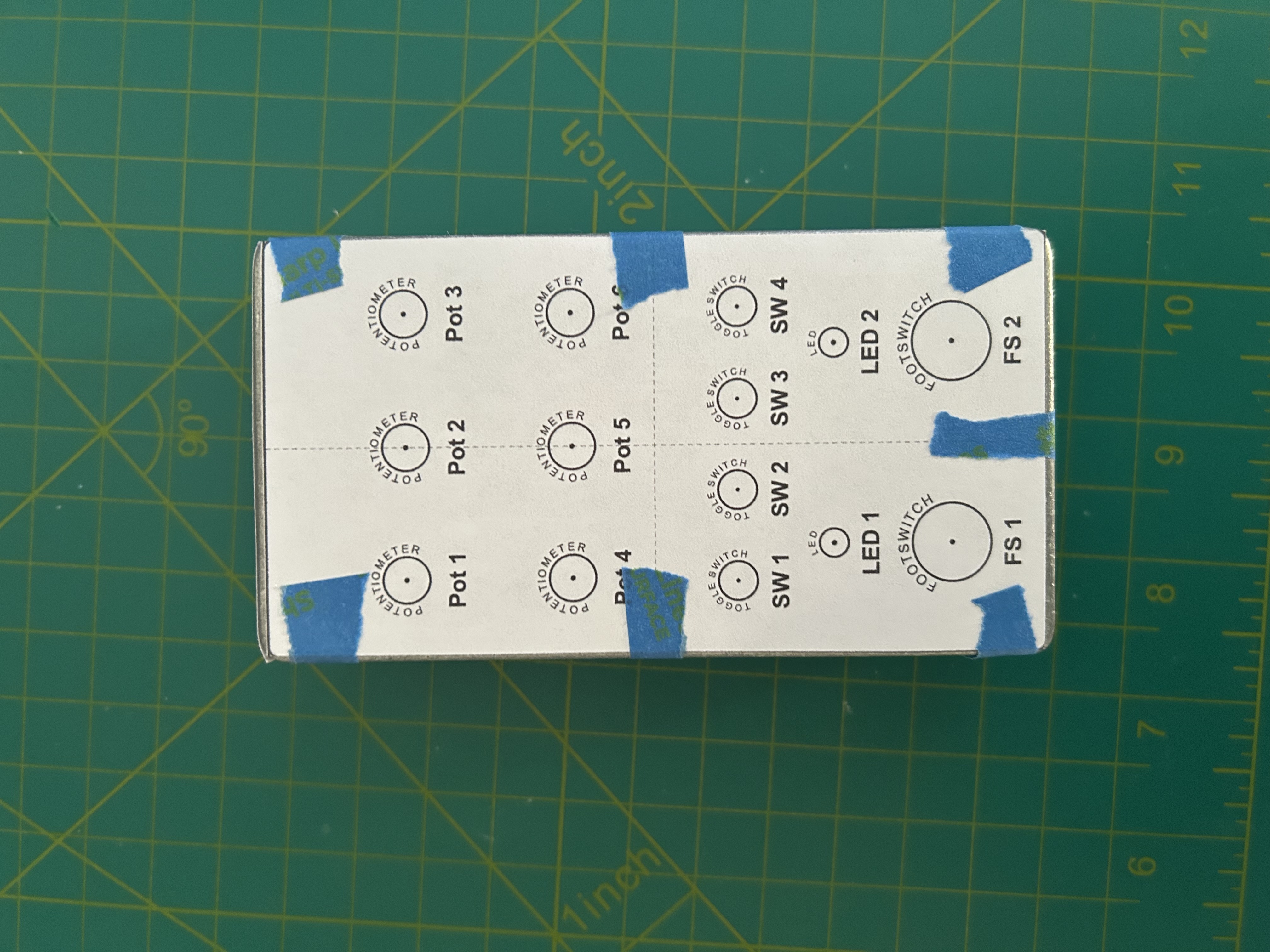
The enclosure needs holes for the 6 different component types: potentiometers, toggle switches, led holders, foot switches, 1/4 jacks, and DC power jack. The drill bits I use for miscellaneous house projects were didn’t give me the size variety I needed, so I picked up a set of cheap drill bits from Harbor Freight with 1/64” increments, which was extremely helpful to match the exact size of each component. This plus my cheap digital caliper from Amazon made the drilling process a breeze.
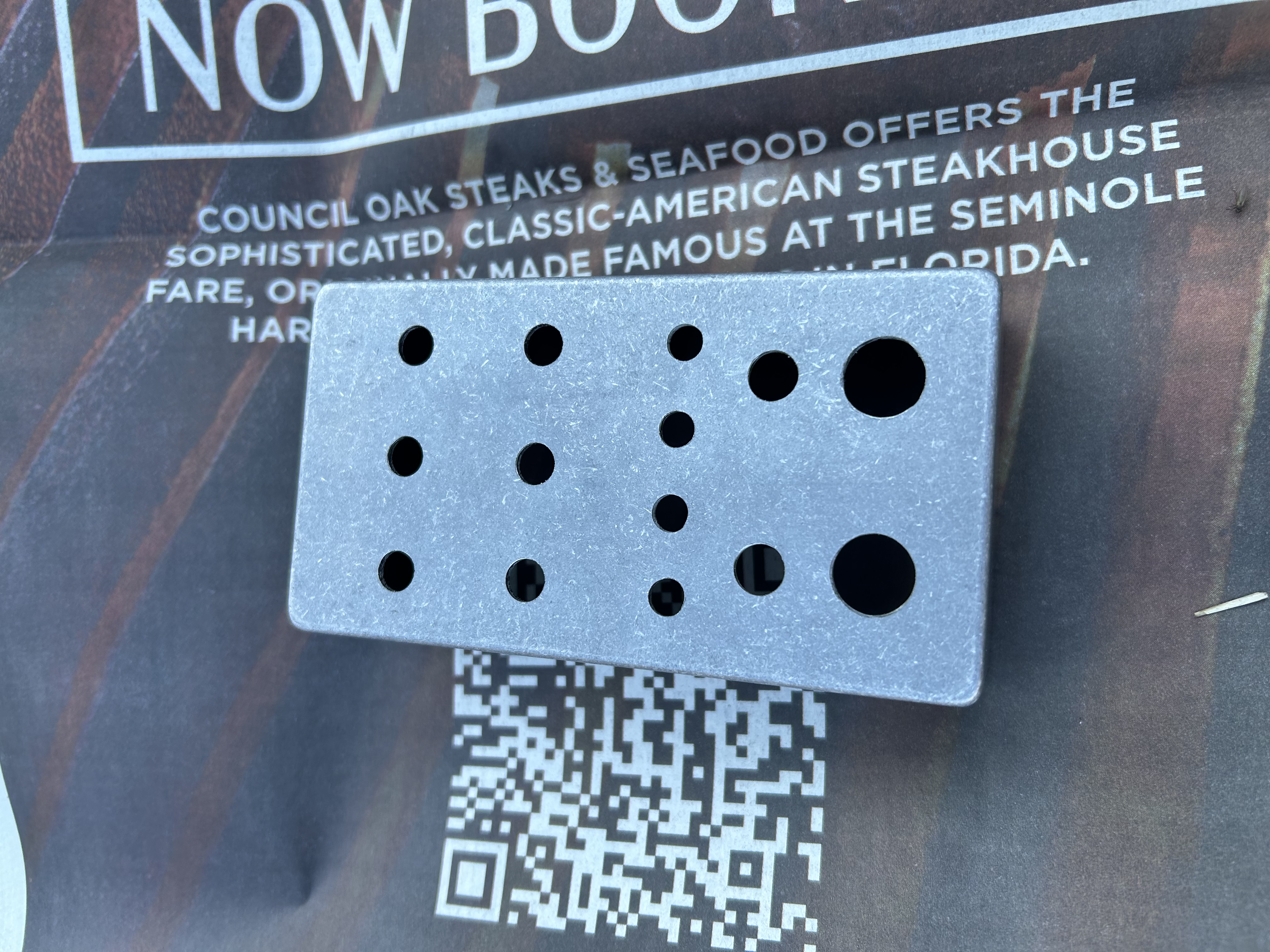
After drilling, I used some white spray paint I found in my garage.
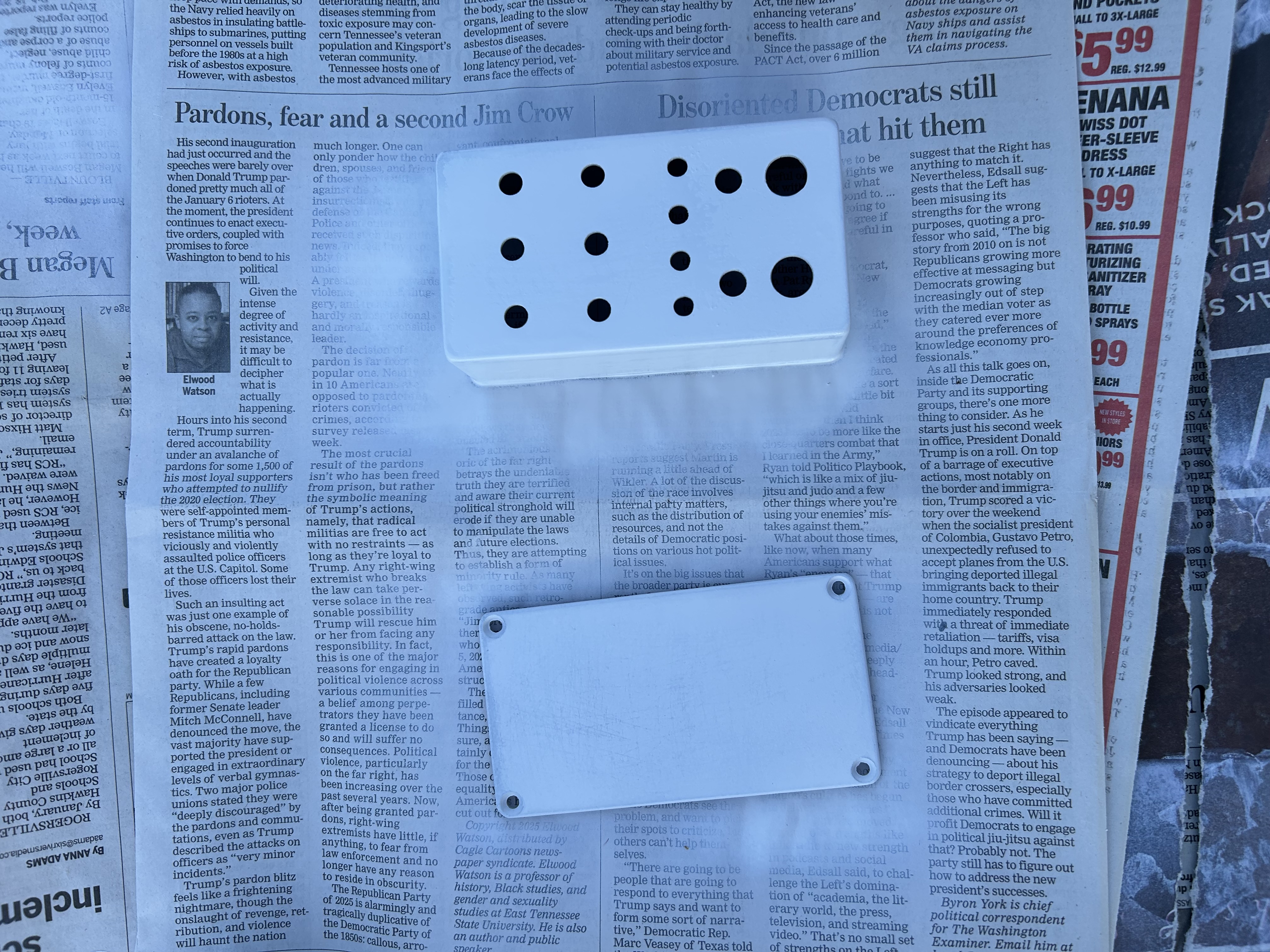
It was hard to get a good coat on the edges and corners of the box, so I ruffed up the entire paint job with a sanding block to get a consistent look.
Step 3: Assemble the Pedal
This is where things get tricky, especially if you don’t plan your approach BEFORE assembling. My approach wasn’t perfect, so you may tackle it differently.
Step 3.1: Add the Easy Components
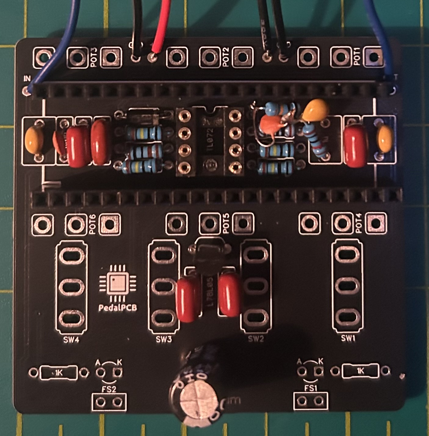
I started by adding the resistors, capacitors, and other straightforward PCB-mounted components. Two notes here:
- The build docs don’t suggest using a IC socket for the TL072 op-amp, but I had some 8-pin sockets lying around and they fit underneath the Seed just fine, so I used one.
- Speaking of things fitting underneath the Seed, I made sure to solder my resistors and capacitors fairly close to the PCB so they weren’t sticking up too much and cause issues with the Seed fit.
Step 3.2: Adding a Low Pass RC Filter
The only tricky part of this stage was adding a low pass RC filter on the Seed’s audio output pin. There are several forums discussing a noise with the Daisy Seed Rev7 (look at the center of your Seed to find this info) when used in the Terrarium circuit.
I followed Gahoo’s suggestion from the the PedalPCB forum, and this provided a significant noise reduction when I was testing this on the breadboard.
Getting it soldered into place was another story. I decided to borrow the ground connection of the 100k resistor to connect the “C” of the RC filter. Here’s a simple sketch of the patch.
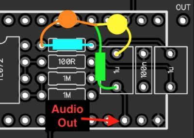
The RC filter is shown in green and orange. Luckily the alloted space for the 1u cap is pretty spacious, so that gave me some extra wiggle room. The RC filter plus the 1u cap connect at a single point, so I brought those three components to the breadboard and solder them together first. Then I brought that 100k resistor and soldered one of it’s legs to my RC cap (orange and blue in the sketch). After that, I brought this mess back to the PCB, and carefully threaded the legs in place, and twisted where need to make room for Seed headers.
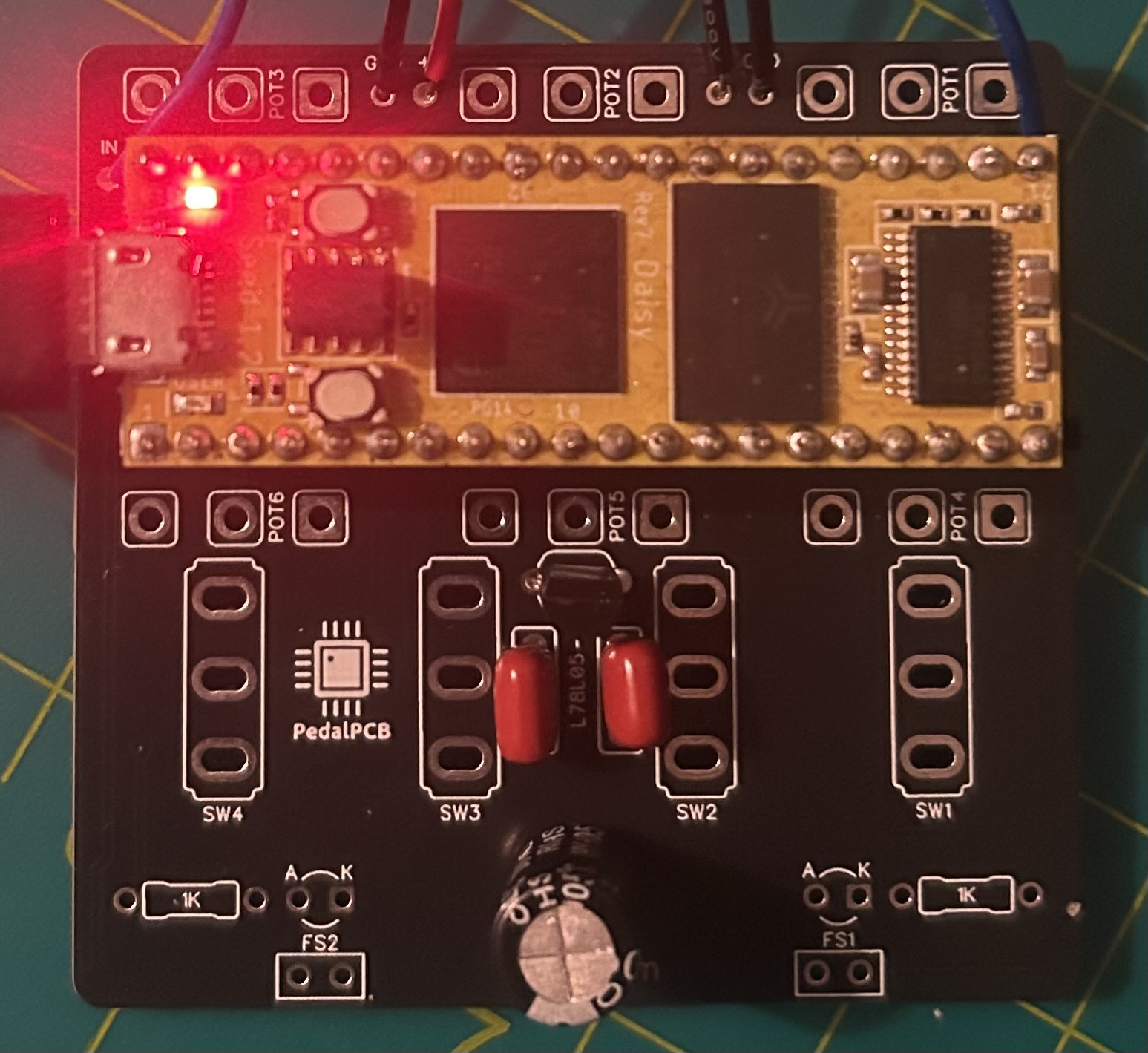
Step 3.3: Add Headers and Check Daisy’s Fit
Next, I added the headers for the Seed. Nothing tricky here, just tried my best to solder them in upright.
I put the TL072 into the IC socket, and pressed the Seed into the headers. At this point, I flashed a simple bypass program to the Seed and ensure things were working correctly before continuing.
Step 3.4: Add Switches
Next came the external components (the things that stick out of the enclosure). I started with the switches because they are very rigid and will set the positioning for the other components.
I read a suggestion on a forum somewhere to “put your components into the enclosure, THEN solder”. I thought that was in reference to making sure you components can fit thru the holes, and since I had already tested that when drilling, I ignored this suggestion, and soldered all my switches to the PCB without using the enclosure. Unfortunately, when I tried to fit the switches into the holes, one switch was way off target. I tried to desolder the switch with no luck (the leads are pretty beefy and I did lots of solder for stability). So instead, I expanded the hole by pressing the drill bit up against the side of the hole in the direction I wanted, and ended up with more of an oval hole than a circle. It’s definitely not a professional approach, but the washer on the switch covers up the excess gap and it still looks fine!
Step 3.5: Add Potentiometers
Next came the pots. I learned my lesson from the switch snafu, and tried to install the pots first, then solder them into the board. But I gave up that idea, as it was impossible to thread 18 pins simultaneously without access to the back panel.
Because the right-angle pots have really long and flexible leads, I decided to risk it, and soldered them in place first, and bend them into the right direction if they didn’t match up. And it worked! I used a small screwdriver to guide the pots into the hole using the notch on top of the knob, but otherwise it went very smoothly.
Step 3.6: Add Top Jacks + Extra Hole
With the top row of pots installed, I now had enough room for the power jack, and two 1/4” jacks.
But before I started tightening things (my switches and pots were still loose), I marked where the micro-usb port of the Daisy Seed was in relation to my enclosure. I took the board out, and cut a hole in the side of the box, so that I can access the Seed without taking it out of the headers.
My power jack has a nut to be tightened from the inside, so I needed to de-solder the socket, thread my wires thru the nut, then thru the enclosure, and re-solder the socket on (I had previously attached the power when testing things earlier, otherwise this would’ve been easier).
The 1/4” jacks were easy, as they are mounted from the inside to the outside, and secured with nuts.
Step 3.7: Add LEDs and Footswitches
Last was the LEDs and footswitches. I’ve seen some people mount the LEDs directly to their enclosure with hot glue, but I picked up some cheap plastic LED holders from AliExpress for this part.
I tightened the switches and pots enough to bring the board closer to the enclosure, and inserted my LED holder + LED from the outside into the board. I held the box up to the light, and while looking thru the footswitch hole, lined up the leads (while making sure to match the anode and cathode to the A and K markings, respectively).
After which, I soldered the wires to my footswitches, and installed them into the enclosure.
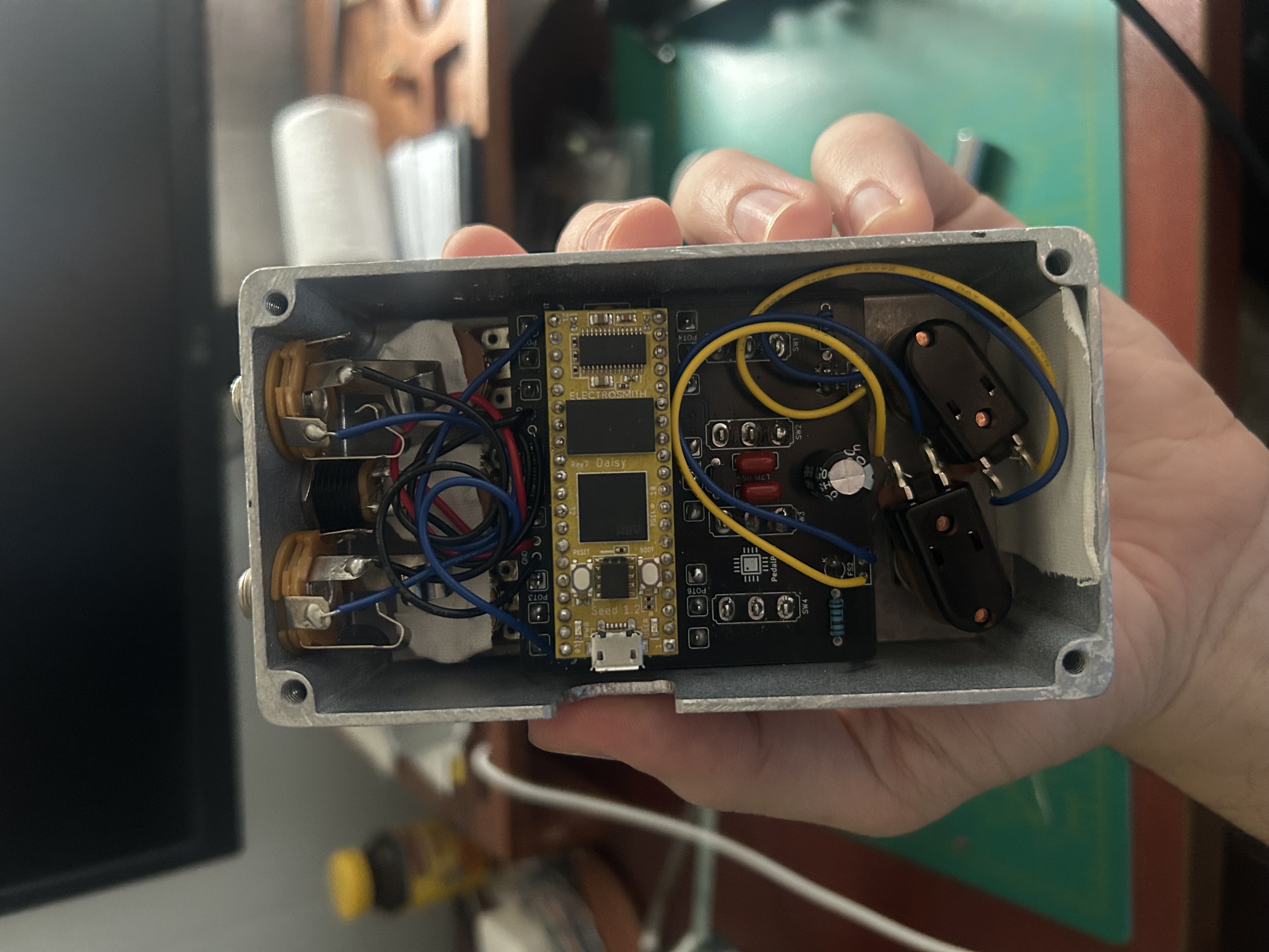
Step 4: Troubleshooting
Hooray! I was very excited to finish the build, and then was extremely disappointed when I flashed a bypass program, and nothing came out the other end. I actually wasn’t able to flash the program to the Seed while it was mounted, which I thought was weird. This turned out to be easy red flag that something is messed up in the circuit, because I was able to flash programs after moving the Seed to the breadboard.
I started troubleshooting by loosely tugging cables, and quickly found that my output jack ground wire was loose (I was actually surprised this was my only soldering mistake). I fixed the connection, and had some success!
Some success? My pedal worked when my jacks were free from the enclosure. As soon as I threaded them thru the box and tightened the nuts, I’d lose audio. After digging around on the internet, I found a possible cause of the issue. Sometimes the jacks will short circuit if the thin wafer separating the tip and sleeve cracks. So as soon as I tightened the nuts, the wafer would split and kill the circuit.
I order new jacks to swap this out, but for now, I just kept the nut on the jack loose, and it works fine!
Next Steps: Programming
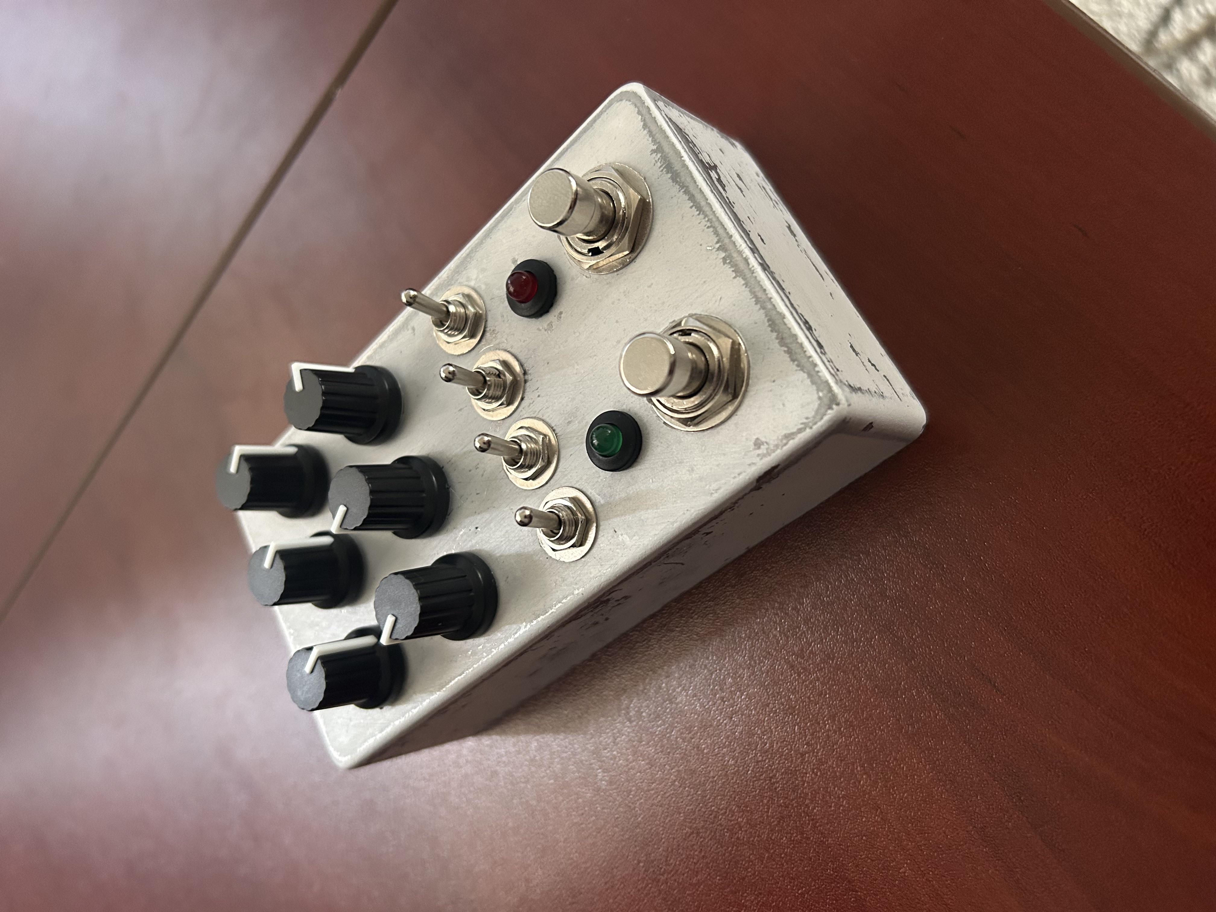
Hardware complete! Now the fun begins, as I decide what my pedal will do. With 6 knobs, 4 switches, and 2 footswitches, the opportunities are endless.
Check out part 2 to see about how I programmed the pedal with multiple overlapping effects and looper functionality (code available).